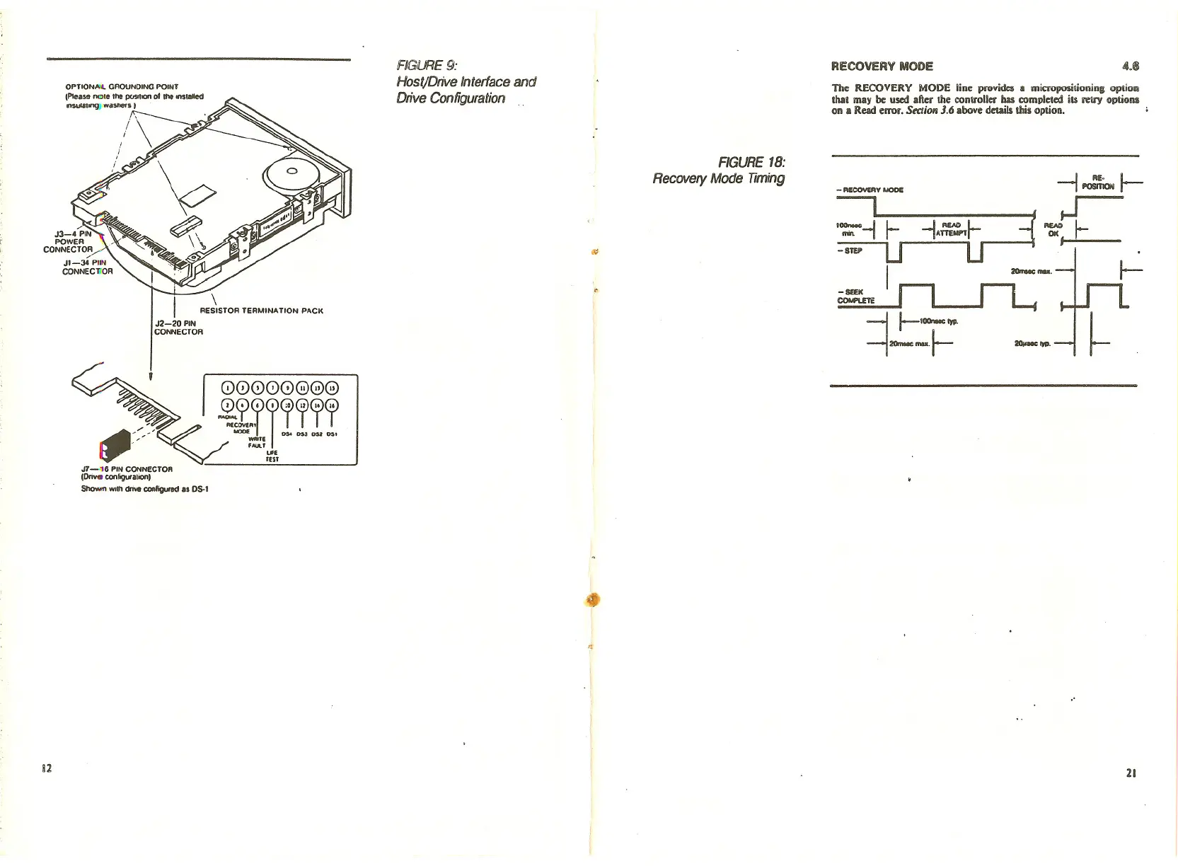
The RECOVERY MODE line provides a micropositionin; option
that may be used after the controller bas completed its retry options
on a Read error. StctiOli
J.6 above details this option.
4.1&
-f~1-
..J
~I-
I _ .•..
-SUI(
COMPI.ETi:
-II-I_~.
-i--+- ~~.
- RECOVERY MODE
'~-1
-SfV'
RECOVERY MODE
FIGURE 18:
Recovery Mode Timing
(i:
FIGURE 9:
Host/Drive Interface and
Drive Configuration
\
• RESISTOR TERMINA nON PACK
J2-2D PIN
CONNECTOR
OPTIONAoI. GROUNDING POINT
(PIe •••• no,. the pcM"," 0111Io ••• 'OIIed
••••••• ,ong; ••aShefI
I
.-/,
J7-16 PIN CONNECTOR
(Dove conligural","'
Shown WI'h drIv. con/igured as OS-I
00000008
~~ITlll:r
un
fES'
4'
i2
21