The DRIVE SELECT line is acUvated by the controller to selccl and
Iddress the drive.
The ST22~ may be confiaured
10 specific iI~ iysiem ll'Cquirem<=llI\l$.
S«tions 3./throuah 3.6 detail the options.
.4.5
DRIVE SELECT
3mO
DRIVE
CONFIGURATION
DRIVE CONFIGURATION SHUNT, J7
3.1
17 is Ii 16-pin ri&hl angle shunl located midway betw«n JI and J2.
Use the provided shoning blocks
10 enable Ihe DRiVE SELECT lines
and the desired oplions. Figure 9 illustrates 17 and indicates Pin I•
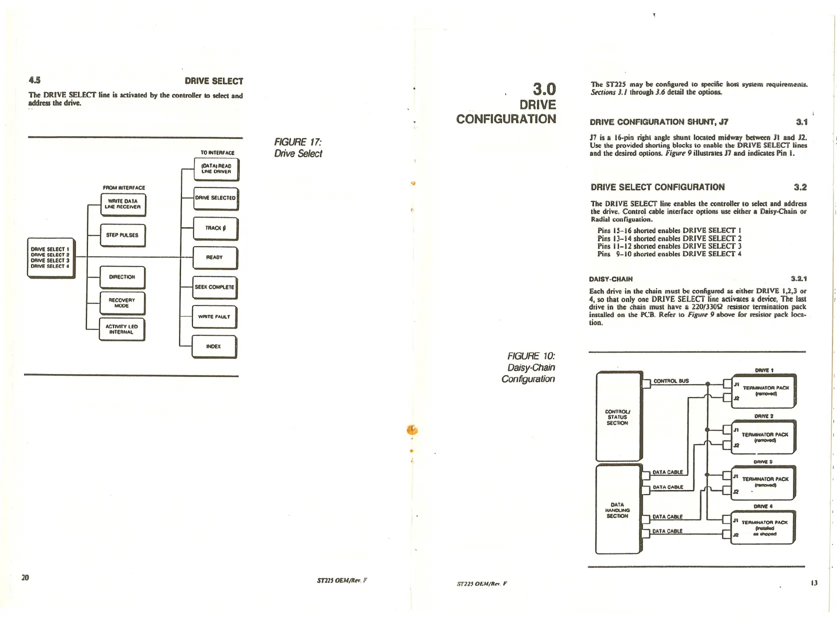
Each drivc in thc chain must be configured a!i either DRIVE 1,2,] or
4, so that onl)' one DRIVE SELECT line activales
II device, The last
drivc in the chain must havc
;II 22013JOQ resistor termination pack
installed on the PCB. Refer
10 Figur~ 9 abovc for resistor pack locz- .
lion.
The DRIVE SELECT line enables the controller 10 select and address
the drive. Control cablc interfacc options use either a Dais)'-Chain or
Radial configuation.
Pins 15-16 shoned enables DRIVE SELECT I
Pins 13-14 shoned enables DRIVE SELECT 2
Pins
i1-12 shorted enables DRIVE SELECT 3
Pins 9-10 shorted enables DRIVE SELECT 4
'I
3.2
:U.1
DIIIVE 1
.11 ~TOR PACK
~
J2
CONTROl BUS
DRIVE SELECT CONFIGURA TIOH
DAISY·CHAIN
FIGURE 10:
Daisy-Chain
Configuration
.~
FIGURE 17:
Drive Select
FROM INTERFACE
ORIY!: SELECT 1
ORIVE SELECT 2
ORIVE SELECT 3
ORIVE SELECT.
(b
..
COHTROLJ
STATUS
SECYlQfO
DATA
HANDLINCI
SECTION
ORM! 2
n_ATOR PACK
(........"
OWM!J
TER ••••••• TOR PACK
~
OlIN!! •
Ji TERMINATOR PACK
.--
J2 --
20
S171J
OEU/~". F
!i1"11.IOEM/It ••. F
JJ