The Radial option is enabled by shoning pins I and 2 at the J7 shunt.
Drives configured to this option are always selected and respond to all
control signals issued on the attached control cable:. The 220/330Q
resistor temnination pack must remam installed on each radially-
connected drive.
F;gu'~/ / iUustrates a host/drive: Radial interconnec-
tion.
JI TEllMINATOR PACK
~
..-
JI TEII•••••••••TOR PACK
In-
..-
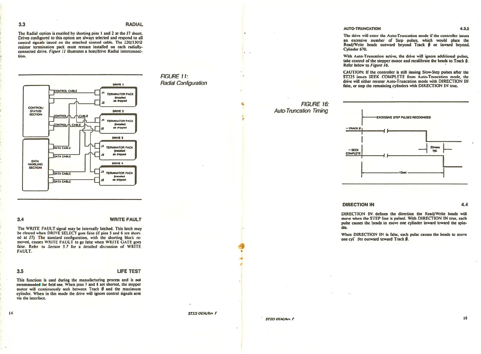
4.:UAUTO- mUNCATION
r--UCESSIV£ STEP PULSES AfCOGHIZ£II
-TRACK': /1 1 _
~I / -J~~
I I_
I--'1- I
The:drive: will enter the Aut()oTruncation mode if the controller issUe:!
an excessive number of Step pulses, which would place the
Read/Write heads outward beyond Track
II or inward beyond.
Cylinder 670.
With Aut()oTruncation active. the drive will ignore additional pulses,
take control of the stepper motor and n:caIibrate the heads to Track ,.
Refer below to
F;gu'~ /6 ..
OunON: If the controller is stiU issuina Slow-Step pulses after the
51225 issues SEEK COMPLETE from Aut()oTruncation mode:. the
drive will either rc:c:nterAuto-Truncation mode with DIRECTION IN
false, or step the remaining cylinders witb DIRECTION IN true.
FIGURE 16:
Auto· Truneation Timing
~
FIGURE 11:
Radial Configuration
RADIAL
DIIIVI 1
DIIIVI 2
DIIIVI S
DIIIVI 4
TER•••••• TOR PACK
r-
..-
JI TEll•••••••••TOR PACK
r-
..-
J2
CONTROI..I
STATUS
SECTION
DATA
HANOUNCJ
SECTIOHI
3.3
DIRECTION IN
4.4
The WRITE FAULT signal may be inlemailylatched.This latch may
be cleared wben DRIVE SELECT gocs false (if pins 5 and 6 are shon-
ed at J7). The standard configuration. with the shoning block re-
moved, cause:s WRITE FAULT to go false when WRITE GATE goes
false. Refer to
See/ion 5.7 for a detailed- di!.;:ussion of WRITE
FAULT .
3.4 WRITE FAULT
CJ
•
DIRECTION IN. defines the direction the ReadfWrite: heads will
move when the STEP line is pulsed. With DIRECTION IN true, each
pulse causes the heads to move one cylinder inward toward the lipiD-
die..
When DIRECTION IN is false, each pulse causes the heads to move
one cyr :I<:routward toward Track _.
. t1'
..
3.5 UFE TEST
This function is used during the manufacturinl process and is not
recommended for Deld use. When pins 7 and 8 are shoned. the stepper
motor will continuously seek between Track _ and the maximum
cylinder. Whc:onin this mode the drive will ignore control signals sent
via the interface.
II)
m1J OEM/It,.,. F
ST11J OEAl/Itrt. F
19