INSTALLATION
MANUAL
Section 2: ELECTRICAL INSTALLATION
2.5 Second Operator Station Connection
This section explains how to connect the 2
nd
Operator Station Kit.
Reference Drawings
90250 Seakeeper 26 Gyro 2
nd
Operator Station Kit
90310 Seakeeper 26 Gyro Cable Block Diagram (includes detail of 2nd Operator Station)
1. DETERMINE LOCATION OF 2
ND
OPERATOR STATION
a. The desired location of the 2
nd
Operator Station must be determined with respect to the
1
st
Operator Station and the vessel arrangement.
b. Typical locations include:
i. Flybridge
ii. Engine room
2. DETERMINE CABLING ARRANGEMENT
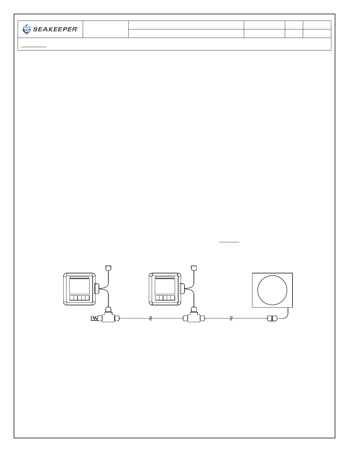
a. Figure 11 below shows the entire serial communications link for 2 Operator Stations.
The Terminator must be installed on the Tee Adapter farthest from the Gyro.
FIGURE 11 – CABLING FOR 2 OPERATOR STATIONS
b. The Operator Station nearest the Gyro Control Box should be connected to CABLE 5.
SEAKEEPER
GYRO
F
F
F M
F
M
1st COLOR
DISPLAY
F
M
"SHIP MONITOR"
F
TEE
ADAPTER
M
"GYRO"
F
F
F M
F
M
2nd COLOR
DISPLAY
F
M
"SHIP MONITOR"
DISPLAY
INTERFACE
CABLE
TERMINATOR,
FEMALE
"GYRO"
CAN CABLE
ASSY, 25m
CAN CABLE
ASSY, 25m
TEE
ADAPTER
DISPLAY
INTERFACE
CABLE
 Loading...