OPERATION
MANUAL
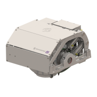
Section 6: GYRO SPECIFICATIONS
Arrangement
The Seakeeper 5000 Gyro consists of the Flywheel, Enclosure, Foundation, Electronics, Brake, Cooling,
and Cover Subsystems.
Installation Location
The Gyro is a torque device and does not have to be installed in a specific hull location or on the
centerline. However, the Gyro should not be installed forward of the longitudinal center of gravity in a
planing vessel where the vertical accelerations exceed ±1 G.
Mounting Dimensions
See Seakeeper Drawing 90293 for bolt-in installation details.
See Seakeeper Drawing 90294 for bond -in installation details.
Loads
The installer is responsible for designing the foundation to which the Gyro is attached and for ensuring
that this foundation can safely transfer the concentrated Gyro loads from the frame to the adjacent hull
structure. Loads that the Gyro imposes on the hull structure are explained on Seakeeper Drawings
90293 and 90294.
Cooling
The Gyro bearings, Motor Drive Box, and hydraulic manifold are cooled by a closed water / glycol mix
cooling loop that incorporates a sea water heat exchanger. The installer is responsible for providing 15 –
30 lpm (4 – 8 gpm) raw water at ambient sea temperature and 1.4 Bar (20 psi) maximum pressure to the
heat exchanger.
Electrical
The installer is responsible for supplying 110-230 VAC, 50/60 Hz, single phase power on a 20A service to
the Motor Drive Box and 12 VDC @ 15A service to the Gyro Control System. Separate circuit breakers
should be used for each Motor Drive Box in multiple gyro installations. Similarly, separate circuit
breakers should be used for each Gyro Control System in multiple gyro installations.