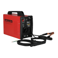
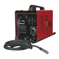
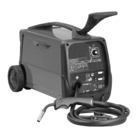
This document provides instructions for the Sealey 140XT and 160XT Arc Welders, which are single-phase transformer-based welding machines designed for stick electrode welding. These models are manufactured to rigorous standards, meeting all relevant CE requirements, and are equipped with a forced air cooling system to enhance duty cycle and performance.
Function Description:
The Sealey 140XT and 160XT are arc welders that utilize a drooping characteristic suitable for welding with alternating current (AC) using stick electrodes. They are designed for various welding tasks, accommodating electrode diameters from 1.5mm up to 4.0mm, depending on the model. The welding current intensity is adjustable via a manually operated magnetic shunt, allowing for fine-tuning of the current to suit different welding requirements. A key feature is the built-in automatic thermostatic protection, which cuts off the power supply and illuminates a yellow light on the front panel if the machine overheats, automatically restoring power once it has cooled.
Important Technical Specifications:
Model 140XT:
- Welding Current: 45-140A
- Electrode Capacity: Ø1.6-3.2mm
- Cooling: Forced Air
- Output Cable: 10mm
- No Load Voltage: 48V
- Power Input: 230V - 1ph
- Weight: 17kg
- Rated No Load Voltage: 48V
- Rated Load Current and Voltage: 140A - 23.6V
- Rated Welding Current (1.5/1.6mm electrode): 45A
- Rated Welding Current (2.0mm electrode): 55A
- Rated Welding Current (2.5/2.6mm electrode): 80A
- Rated Welding Current (3.2mm electrode): 115A
- Average Duration of Welding Time (Tw S): 3600 (1.5/1.6mm), 728 (2.0mm), 186 (2.5/2.6mm), 89 (3.2mm)
- Average Duration of Re-establishment Time (Tr S): 0 (1.5/1.6mm), 292 (2.0mm), 327 (2.5/2.6mm), 370 (3.2mm)
- Effective Input Current (I1eff): 14.1A
- Maximum Current Absorbed from Mains (I1max): 31A
- Insulation Grade: H
- Case Protection Class: IP21S (No object including fingers less than 12.5mm can be inserted into case. Vertically descending water droplets shall not enter the case. Water test conducted with moveable parts at a standstill.)
Model 160XT:
- Welding Current: 55-160A
- Electrode Capacity: Ø2.0-4.0mm
- Cooling: Forced Air
- Output Cable: 10mm
- No Load Voltage: 50V
- Power Input: 230V - 1ph
- Weight: 18kg
Both models feature a double-vented, wraparound shell fitted to a heavy-duty chassis and are supplied with an accessory kit including an electrode holder, earth clamp, and chipping hammer/wire brush.
Usage Features:
- Current Regulation: The welding current is adjusted using a control knob on the front panel. Turning the knob clockwise increases the current, while turning it anti-clockwise decreases it. It is crucial to set the desired current level before commencing welding and avoid operating the mechanism during welding.
- Thermostatic Protection: A yellow light on the front panel indicates overheating, and power is automatically restored once the unit cools down. Larger welding rods require higher currents, which can lead to more frequent cut-offs due to overheating.
- Setting Up: Before welding, ensure the machine is off. Attach the earth clamp to a clean, ground point on the workpiece, as close as possible to the welding area. Select the appropriate electrode diameter based on the weld type (higher currents for flat welding, lower for vertical/overhead). Insert the electrode into the holder, ensuring a good connection.
- Commencing Welding: Practice on scrap metal is recommended. Always wear a full face welding mask, gauntlets, and protective clothing. Goggles should be worn when chipping slag.
- Striking the Arc: Tap the electrode lightly on the workpiece like striking a match. Avoid hitting the workpiece to prevent damage to the stick.
- Maintaining the Arc: Once the arc is struck, maintain a steady gap between the electrode and workpiece, equal to the electrode's diameter. Hold the electrode at a 20°-30° angle from the vertical.
- Finishing the Weld: At the end of a bead, move the electrode tip backward to fill the crater, then quickly lift the electrode to extinguish the arc.
- Electrode Sticking: If the electrode sticks, pull sharply left then right to free it.
- Post-Welding: Chip off slag with a chipping hammer (wearing goggles). Switch off the welder and disconnect from the mains. Use pliers to handle hot electrodes or welded pieces. Remove the electrode from the holder as a safety precaution.
Maintenance Features:
- General Cleaning: Keep the welder clean and dry. Use a dry cloth for cleaning.
- Electrode and Cable Inspection: Ensure all electrodes are clean and dry, and all cables are in good condition.
- Regular Inspection: Inspect the welder regularly, depending on usage and environmental dustiness. Remove dust deposits from the transformer using dry compressed air (max 10bar).
- Electrical Connections: Verify that electrical connections are tight and check wiring for insulation damage.
- Lubrication: If necessary, apply a thin layer of high-temperature grease to lubricate moving parts of the regulators (threaded shaft, sliding surfaces, shunts).
- Reassembly: After maintenance, ensure all covers are replaced and fastening screws are tightened.
- Professional Service: For any other maintenance or service requirements, use an authorized service agent. Never perform welding operations with covers removed.
Electromagnetic Compatibility (EMC):
The equipment conforms to European standards for electromagnetic compatibility of arc welding equipment. Users are responsible for installing and using the equipment according to instructions to minimize interference. If disturbances occur, remedial actions may include earthing the circuit, constructing an electromagnetic screen, or using input filters.
- Assessment of Area: Before installation, assess potential electromechanical problems in the surrounding area, considering other supply cables, control cables, radio/television transmitters, computers, safety-critical equipment, health of people (pacemakers), calibration equipment, immunity of other equipment, and time of day for welding activities.
- Mains Supply: Connect to the mains supply as instructed. Additional precautions like filtering or shielding the supply cable may be necessary if interference occurs.
- Maintenance: Routinely maintain the equipment. Ensure all access and service covers are closed and fastened during operation. Do not modify the equipment except as instructed.
- Cables: Keep welding/cutting cables as short as possible and positioned close together, running at or near floor level.
- Equipotential Bonding: Consider bonding all metallic components in the welding/cutting installation. However, ensure the operator is insulated from bonded metallic components to prevent shock.
- Earthing of Workpiece: It is important to separately bond the workpiece to earth in addition to the welder/cutter return cable. This can reduce emissions.
- Screening and Shielding: Selective screening and shielding of other cables and equipment in the surrounding area may alleviate interference. Screening of the entire welding/cutting installation may be considered for special applications.