To fit mains power plug see chapter 1. Note: you will need a 30amp electrical supply for higher power 0.8mm & 1.0mm settings.
3. 1. Wheel Assembly
3. 1. 1.
Turn the machine upside down.
3. 1. 2.
Remove the screws attached to the bottom front of the machine and use them to attach the front castor wheels.
3. 1. 3. Fit the large rear wheels to the rear axle with the split pins provided.
NOTE: be sure the wheel washers are fitted between the wheels on the axle.
3. 1. 4. Mount the complete axle assembly on to the rear of the welder body.
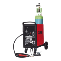
3.2. Connecting the gas cylinder
3. 2. 1. When using Argon or Argon mixtures you will need to use the bull nose adaptor. If you intend to use CO2 gas the
regulator will fit directly onto the cylinder.
3. 2. 2. Screw the bull nose adaptor to the cylinder with a spanner.
3. 2. 3.
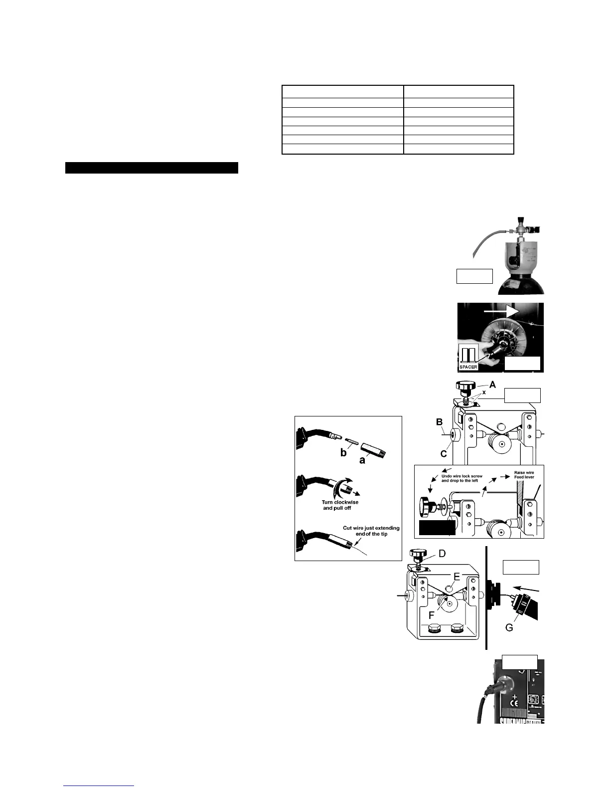
Fit the gas regulator on to the bull nose adaptor and connect it to the machine gas hose (fig.1).
3. 2. 4. Set the regulator flow rate to 5-8 litres/min depending on the material to be welded, and whether there are draughts
which are strong enough to disturb the gas flow.
3. 3. Fitting a reel of wire
Wire capacity: (Mild Steel).......5 to 15 kilos.
3. 3. 1. Push the reel of wire over the reel holder end spring and onto the reel holder ensuring the spool rotates clockwise,
with the wire drawing off the reel from the top (see white arrow in fig 2). Large spools of wire have a guide hole which
must be pushed onto the plastic pin located at the end of the reel holder. This pin will stop larger reels from free
wheeling around the holder.
3. 3. 2. To secure the reel of wire take the plastic spacer and gently open the diameter of the spacer whilst placing over
the reel holder end spring and onto the reel holder (fig 2).
3. 3. 3. Undo the wire lock screw (fig 3 A) and slide to left, and raise the wire feed lever to the right (fig 4).
3. 3. 4. Straighten about 40-50mm of wire and gently push the wire through the brass guide (fig 3. B & C) into and through
the correct size feed roller groove, and on through the second brass guide into the torch.
3. 3. 5. Lower wire feed lever and clamp with the wire lock screw. Ensure the screw spring and washer are between
the head of the screw and the top of the feed lever (fig 3 x).
3. 3. 6. Remove gas cup (fig 3.3.6. a) and contact tip (b) from end of torch as follows:
a) Take torch in left hand with the torch tip facing to the right.
b) Grasp gas cup firmly in your right hand.
c) Turn gas cup clockwise only (c) and pull cup out to the right.
p WARNING! do not turn gas cup anti-clockwise, as this will
damage the internal spring.
d) Unscrew the copper contact tip (right hand thread) to remove.
3. 3. 7. Check welder is switched off 0, and that the earth clamp
is away from the torch tip. Connect the welder to the mains
power supply and set the voltage switch to one.
3. 3. 8. Set the wire speed knob to position 5 or 6. Keeping the torch
cable as straight as possible and press the torch switch.
The wire will feed through the torch.
3. 3. 9. When wire has fed through, switch welder off, unplug from mains.
a) Take torch in left hand and screw contact tip back into place.
b) Grasp gas cup in right hand, push onto torch head and
turn clockwise only.
p WARNING! do not turn gas cup anti-clockwise, as this will
damage the internal spring.
c) Cut wire so that it is just protruding the cup.
3. 4. Setting wire tension
It is important to set the correct tension (fig 5 F), too little or too much tension will cause problematic
wire feed and result in poor welding.
3. 4. 1. For 0.6mm wire in mild steel the wire lock screw should be tightened fully and then undone
approximately two turns (fig. 5 D).
3. 4. 2. Correct tension between the rollers is checked by slowing down the wire between the fingers.
If the top feed roller (fig 5 E) skids the tension is correct. T
ry to use as low a tension as possible,
for too high a tension will deform the wire and may result in a blown fuse.
3. 5. Clutch adjustment
It is essential that the clutch is adjusted correctly.
3. 5. 1. Once the wire is fed through the torch, switch on the machine and set the wire speed to maximum.
3. 5. 2. Depress torch switch and release quickly. If the spool overruns it indicates that the clutch is too loose.
3. 5. 3. Tighten the clutch (located in the centre of the wire spool holder) with a socket spanner and test the machine as above
until the wire stops over running.
NOTE: DO NOT OVER TIGHTEN THE CLUTCH AS THIS WILL CAUSE WIRE FEED PROBLEMS.
3. 6. Euro Connection
This welder is fitted with a Euro Connection quick release torch. (fig 6).
3. 6. 1. Simply line the pins in the torch up to the appropriate holes in the machine, push in and tighten with the knurled knob
(fig 5 G). Remember to remove the Torch after welding is completed and store in a safe dry place.
Note: Accidental damage to your torch is not covered by the guarantee.
3. ASSEMBLY
Fig 1.
MODEL 250/10 IS EQUIPPED WITH: 30.8mm Torch, 3Mini reel of 0.8mm wire, 30.8/1.0mm feed roller 3Regulator, 3Gas hose.
To weld with 0.6mm wire, order a reel of 0.6mm wire, and 0.6mm feed roller. To weld with 1.0mm wire, order a reel of 1.0mm wire
(The 250/10 is designed to accommodate 15kgs capacity 0.8mm & 1.0mm wire).
Your Supermig is designed to operate with three diameters of welding wire: 0.6mm, 0.8mm & 1.0mm wire, and will accommodate
a capacity range of 5 to 15Kgs.
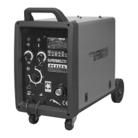
Model Number SUPERMIG 210/10
Welding Current 35-250 Amps
Duty Cycle 100% @ 60A
50% @ 120A
20% @ 195A
15% @ 230A
Power efficiency 6.5 Kva
Welding
Capability
Chart:
SUPERMIG 250/10 - Job181 -280198
Fig 2.
Fig 3.
Fig 5.
Fig 6.
Fig 4.
Fig 3.3.6.
c
 Loading...