Rated on-load voltage U
o
in V
a) Peak value in case of direct current;
b) Peak & r
.m.s. value in case of alternating current.
Direct current
Fuse
X Duty cycle (Factor)
1
2
Rated weld current
U
2
Conventional load voltage
Mains supply and number of phases
(i.e. 1 or 3) with symbol for
alternating current.
(1)3
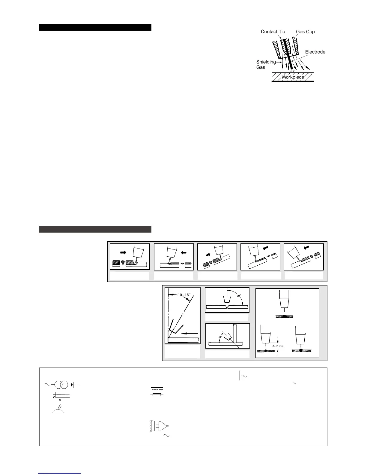
5. VARIOUS WELDING METHODS
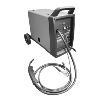
4. MIG/MAG WELDING
Principles
A spool of welding wire is positioned on the welders spool holder and automatically fed through
an insulated liner in the torch to the tip. The torch assembly consist of a switch, liner, gas hose,
and control cable. The switch activates the wire feed roller and the gas flow. Conversely, releasing
the switch stops the wire feed and gas flow. The weld current is transferred to the electrode (the wire)
from the contact tip at the end of the torch. A gas cup fits over the contact tip to direct the gas flow
towards the weld ensuring that the arc welding process is shielded from oxidising air contaminates.
The shielding gas also assists heating of the weld materials. The torch is connected to the positive
side of a DC rectifier, and the negative clamp is attached to the workpiece.
Preparation for welding.
IMPORT
ANT: Welder must be switched off at the mains before starting. If welding a vehicle, disconnect battery or fit an electronic circuit protector.
4.1. Connecting the Earth Lead
To ensure a complete circuit, the earth lead must be securely attached to the work piece that is to be welded.
4.1.1. The best connection is obtained by grinding clean the point of contact on the workpiece before connecting the earth clamp
to the job to be welded.
4.1.2. The weld area must also be free of paint, rust, grease, etc.
4.1.3. When welding a vehicle, be sure the vehicle battery is disconnected or fit a PROSAF/12V or 24V Electronic Circuit Protector
available from your Sealey dealer.
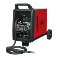
4.2. Setting Up
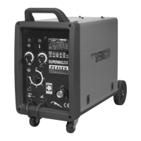
The Supermig250/10 has an automatic wire speed system, which for most effective welding should be set up as follows:
4.2.1. Select the voltage step that best suits the thickness of the material to be welded
4.2.2. Adjust the wire feed knob until a perfect weld bead is obtained.
NOTE: If the wire speed increases, even to reaching maximum, do not be concerned as the wire speed setting will re-adjust
correctly to any voltage step selected thereafter.
4.3. Welding mild steel
To weld mild steel you can use CO2 gas for most tasks where spatter and the high build up of weld do not pose a problem.
To achieve a spatter free and flat weld, you must use an Argon/CO2 mixture.
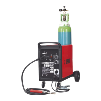
4.4. Welding aluminium
To weld aluminium use: 3 Argon gas, 3 0.8mm Contact Tip (AK957), 30.8mm Aluminium Wire, (MIG/2/KAL08).
Alternating current & the rated
frequency in hertz i.e. 50Hz
P
max
... kW
Maximum power consumption in case
of a rotating welding power source. This
value will only be given when it is not
combined with a prime mover.
U
1
... V/...Hz
Rated values of the supply voltage
and the frequency
.
/
1
Rated supply current.
IP Degree of protection, i.e. 21 or 23.
ED%
Duty cycle
%
The position of the torch,
its angle and direction of travel
in relation to the workpiece
is essential for the appearance
and quality of the weld.
The illustrations demonstrate
various positions and directions.
Rightward Welding
Welding in general
W
elding with a long arc reduces penetration and widens
the arc.
This in turn results in more spatter
.
A long welding arc can be appropriate for welding butt
joints in thin materials.
Welding with a short arc (at the same weld settings)
results in greater penetration and a narrower weld
and reduces the amount of spatter.
Leftward Welding
Vertical Rightward
Downhard leftward
Down Rightward
1. Direction of
Welding
3. Fillet Weld
3. Butt Weld
Normal
Welding
Arc
Long
Welding
Arc
Short
W
elding
Arc
MEANINGS OF MARKINGS, AND SYMBOLS
Single Phase transformer & rectifier
Flat Characteristic
MIG/MAG welding
...A/ ... V to ...A/ ... V Range of output, rated min
& max welding current and
their corresponding conventional
load voltage.
PA kVA Power Efficiency
SUPERMIG 250-Job181-280198
 Loading...