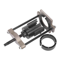
Fig.2
Fig.4
Fig.3
Fig.5
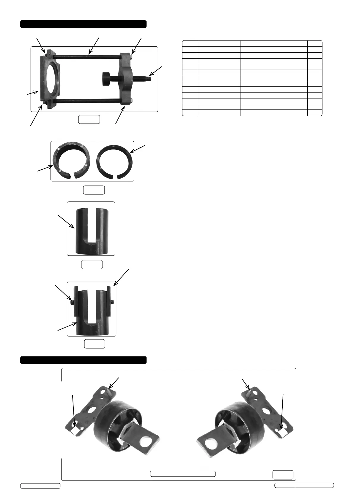
5. BUSH REMOVAL
Item Part Number Description Qty
1 VSE4784-01 Adaptor 1
2 VSE4784-02 Depth Control Legs 2
3 VSE4784-03 15mm 'C' Ring 1
4 VSE4784-04 35mm 'C' Ring 1
5 VSE4784-05 Press Fame Top Plate 1
6 VSE4784-06 Press Frame Bottom Plate 1
7 VSE4784-07 Distance Studs 2
8 VSE4784-08 Spacer 2
9 VSE4784-09 Thrust Screw (M20 X 1.5) 1
10 VSE4784-10 Nut M12 4
11 VSE4784-11 Plain Washer ø12 4
12 VSE4784-12 M8 X 16 Screw 2
Rivet stud
4. CONTENTS
VSE4784 Issue No.2 - 07/11/16
Original Language Version
© Jack Sealey Limited
7
10,11
10,11
8
6
5
9
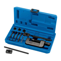
4.1 15mm Magnetic 'C' Ring (Fig.3 item 3)
A distance piece used in the bush extraction
process only,
integral magnets holds the ring in place.The slot in the ring clears
the obstruction of the hose bracket.
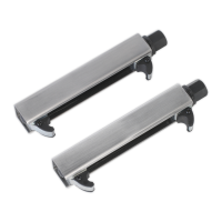
4.2 35mm Magnetic 'C' Ring (Fig.3 item 4)
A distance piece used in the new bush insertion
process only,
integral magnets holds the ring in place. The slot in the ring
clears the obstruction of the hose bracket.
3
4
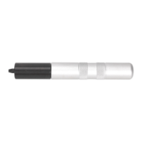
4.3 Adaptor (Fig.4 item 1)
90mm Diameter x 115 long. Slotted, counterbored and recessed
to accommodate extraction and insertion of the bush.
4.4 Depth Control Legs (Fig.5 item 2)
TwoSegmentsnesteithersideoftheadaptorxedwithM8
screws. Only used when inserting new bush to correct
depth.
1
2
12
1
Rivet stud
R
L
BushAssemblyIdentication
Nearside
Offside
Fig.6
I/D Stamped
I/D Stamped