Do you have a question about the Sealey VSE4784 and is the answer not in the manual?
Adherence to workshop practices, familiarisation with hazards, and user care.
Key safety advice including torque limits, lubrication, and hazard warnings.
Suitable for rear trailing arm bush removal/installation on Ford vehicles.
Lists compatible Ford and Volvo models for the trailing arm bush tool.
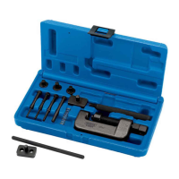
Lists all parts included in the trailing arm bush tool kit with part numbers.
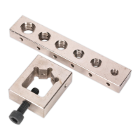
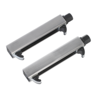
Details specific components like 'C' rings, adaptor, and depth control legs.
Steps for vehicle preparation, suspension support, and clearing the work area.
Noting the orientation of the existing bush before removal.
Detailed steps for using the tool to extract the bush from the housing.
Cleaning the housing bore and positioning the new bush and depth control legs.
Placing the 35mm 'C' ring onto the trailing arm to clear the handbrake bracket.
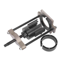
Using the press frame and adaptor to insert the new bush to the correct depth.
Steps after insertion, including tool removal, cleaning, and vehicle refitting.
Thoroughly clean components, especially thrust screw threads, and inspect for damage.
Smear with oil, store indoors, and keep the carry case closed to prevent condensation.
This document describes the Sealey Trailing Arm Bush Tool for Ford Mondeo Mk4, Model No: VSE4784.
The Sealey VSE4784 is a specialized tool designed for the removal and installation of rear trailing arm mounting bushes on Ford vehicles, specifically the Mondeo Mk4, S-Max, and Galaxy models. It is also suitable for certain Volvo vehicles (S60, S80, XC60, V70, XC70 from 2006-2009) that share the same Ford platform. A key feature of this tool is its ability to perform these operations in situ, meaning the trailing arm does not need to be removed from the vehicle. This can significantly reduce labor time and complexity. The tool facilitates both the extraction of old bushes and the insertion of new ones, ensuring correct depth and alignment.