12
SEASTAR Hydraulics
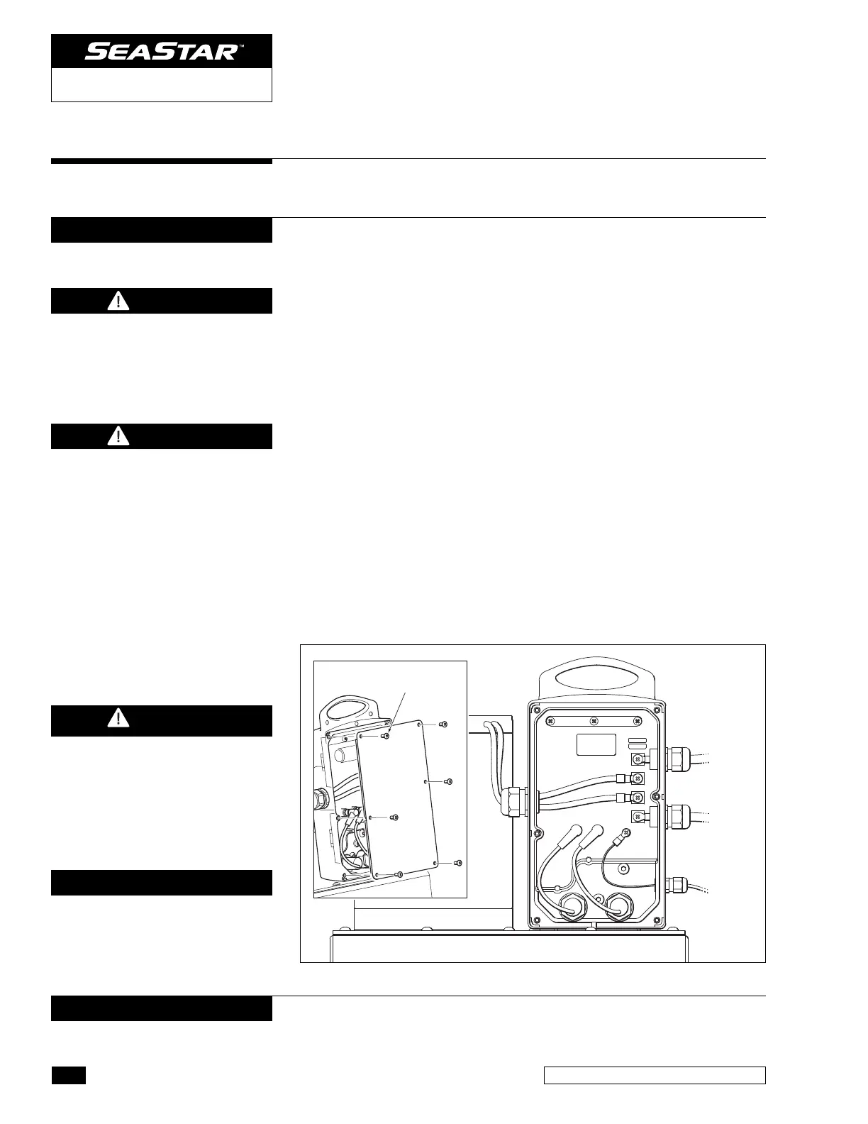
BATTERY
+
BATTERY
–
IGNITION
SIGNAL
+
COVER SCRWS
PHILLIPS (6)
NOTICE
Step 2 Electrical Connections
Figure 11.
DC Power Unit Battery Connections
It is recommended that the DC Power unit be connected directly to
a main battery, or other on-board 24-volt power source rated for 90
amps peak using an appropriate fuse or breaker.
1 Remove electronics casing cover by removing the 6 Phillips head
screws. (Refer to Figure 11.)
2 Insert positive batter y lead through the upper strain relief fitting
on the electronics box. (Refer to Figure 11.)
3 Remove the #10 Phillips head screw from the top-most terminal
inside the electronics enclosure. Securely fasten the positive
lead with ring connector to this terminal post, torque to 25in-lbs.
4 Insert negative batter y lead through the lower strain relief fitting
on the electronics box. (Refer to Figure 11.)
5
Remove the #10 Phillips head screw from the bottom-most terminal
inside the electronics enclosure. Securely fasten the negative
lead with ring connector to this terminal post, torque to 25in-lbs.
6 Using a crescent wrench, tighten the strain relief nuts until the
rubber sleeves form a seal with the wires. DO NOT OVER TIGHTEN.
7 Connect the other ends of your battery leads to your breaker
box, battery, or other 24V power source rated for a minimum of
90A peak current.
8
Leave the electronics cover off for the moment, you are not finished.
To avoid risk of fire, ensure that
the area in which any electrical
connection is being made is
vented and free of any fumes
that may cause fire or explosion.
WARNING
DO NOT REVERSE POLARITY.
The use of color coded (Red/
Black) wiring is highly recom-
mended to avoid reversing
polarity. Failure to comply may
result in damage to the unit.
WARNING
To avoid fire and/or poor
steering performance, ALL
electrical connections and
cable MUST comply with ABYC
wiring standards, be rated for
105 degrees C, and compliant
with SAE J1128. Battery leads
must be a MINIMUM of 6AWG
and a MAXIMUM of 30ft in
length, with an appropriate
fuse or breaker for fire
protection. If your application
requires longer battery leads,
please consult factory.
WARNING
NOTICE
It is recommended that ring-type
crimp connections are used at
each
end of the battery harness.
Use the correct ring terminal for the wire
gauge, and the appropriate crimping pliers.
2.1
DC POWER STEERING UNIT
NOTICE
Battery connections inside the
electrical
box should be made
using ring terminals sized for a
#10 stud.

 Loading...