On the lower side of case there are the outputs (with cable gland) for connections with combined
sensors.
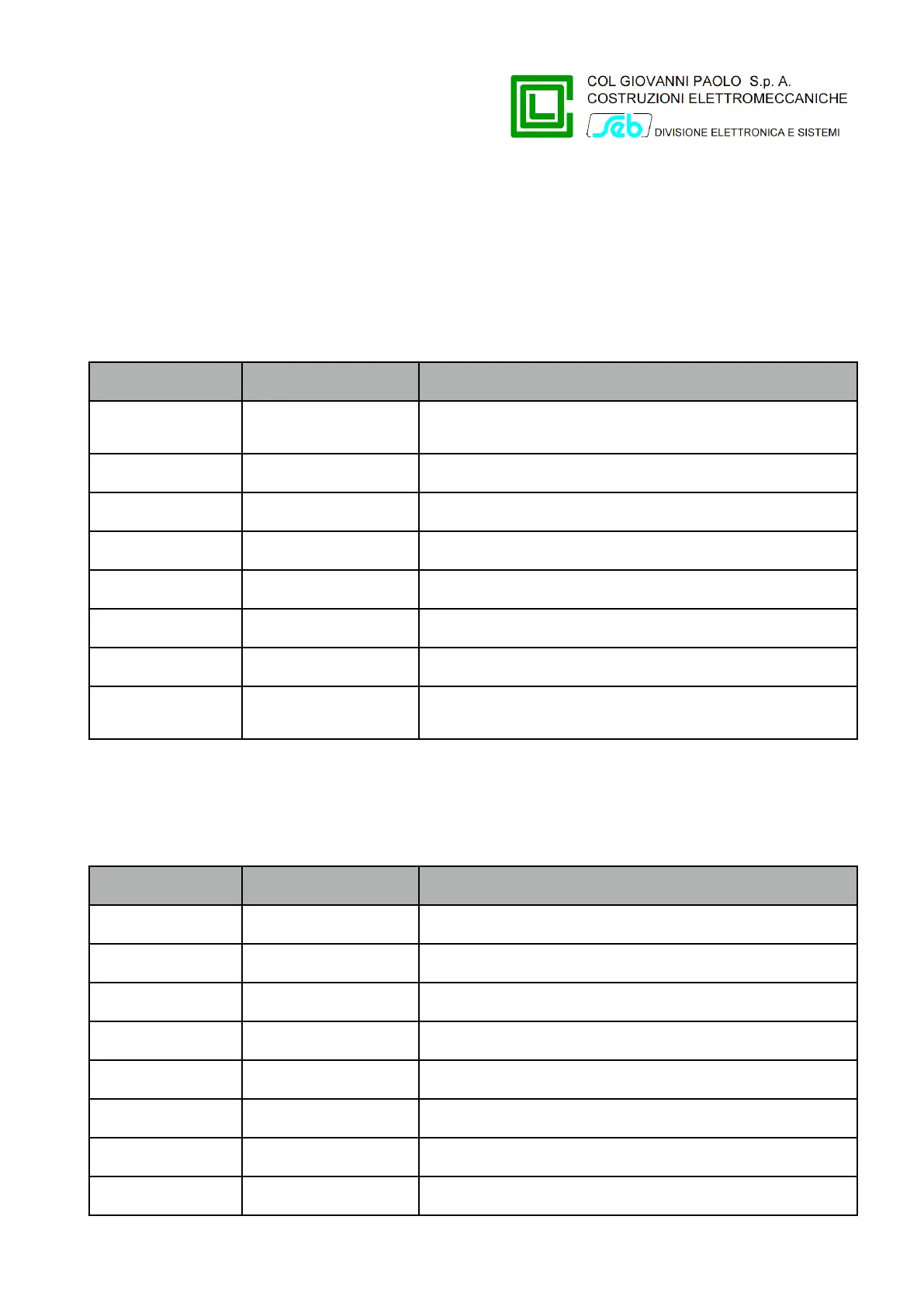
Terminal blocks
Terminal block MA
It is the terminal block on which you connect the voltage signals and current signals by combined
sensors.
Current sensors common connection (connected
to ground)
Voltage sensors common connection (connected
to ground)
Terminal block MB
It is the terminal block used by the connection cable to the remote control system. There are the
power supply inputs, the outputs relay signals, the 4-20 mA current outputs and the inputs to reverse
surveillance direction of directional earth fault protection.
Power supply input (+24V)
4÷20 mA current output (+)
4÷20 mA current output (-)
Reverse signal digital input
P515D851 Rev. E November 2019 Pag. 15 of 45