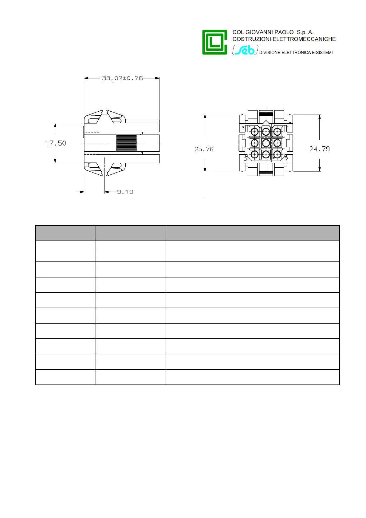
Signals are placed on the connector to the remote control system according to the following table:
Power supply input (+24V) and remote signals
reference
4÷20 mA current output (+)
4÷20 mA current output (-)
Reverse signal digital input (common)
Reverse signal digital input
Power supply input (GND 24V)
Connection with combined sensors
To facilitate the connection between the cables of the combined sensors and the RGDAT-A70, this
one is supplied with a proper adapter; one side of the adapter is connected to the terminal block MA
and the other side has 3 connectors RJ45 to plug the cables of the combined sensors.
The adapter is factory connected to terminal block MA.
Each RJ45 connector has a label to indicate the related phase.
The following image refers to the above indicated arguments.
P515D851 Rev. E November 2019 Pag. 17 of 45