Do you have a question about the Sebart Mig29 3D-EDF and is the answer not in the manual?
Li-Po battery types for optimal performance.
Important safety notice regarding misuse.
Wiring the 7-channel receiver to all servos.
Details servo connections for flight controls and aux functions.
Specifies the recommended CG point for balance.
Setting servo direction for flight controls.
Fine-tuning servo throw limits for each control.
Adjusting servo neutral points for precision.
Important note on gyro self-setting time.
Adjusting thrust vector servos for proper centering.
Adjusting aileron servos to their neutral position.
Adjusting elevator servos and linkage length.
Using sub-trim to center vektor servos.
Programming for responsive 3D power.
Setting up three distinct flying modes.
Full rates, gyro on.
Mixing for enhanced knife-edge flight.
Adjusting the main gyro sensitivity setting.
Enabling the gyro mixing function.
Mixing gyro input to the gear channel for hovering.
Verifying radio transmission range.
Ensuring all surfaces move correctly.
Final note on gyro readiness.
Steps to resolve gyro flashing light.
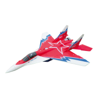
| Motor | Brushless outrunner |
|---|---|
| EDF Diameter | 70mm |
| Servos | 5 micro servos |
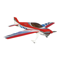
| Wingspan | 890mm |
| Flying Weight | 1400g |
| EDF Unit | 70mm EDF |
| Radio | 4+ channels |