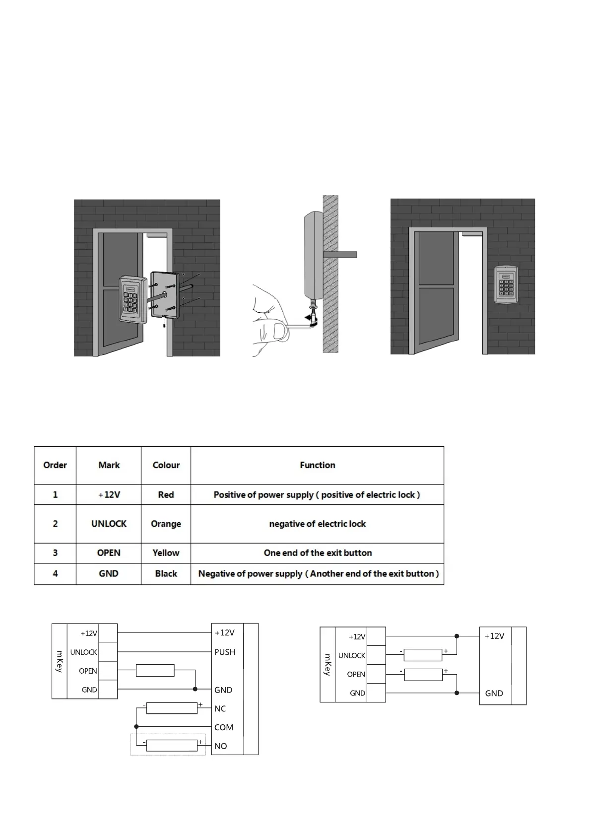
2.2Wiring
According to the selected wiring diagram, connect the four lead wires to the system cable one by
one, and then insert one end of the plug into the 4P socket of the access control, taking care not
to short circuit, otherwise the power may be burned out. Please Check and briefly power on to test
if the indicator light is normal, and whether the buzzer will beep once, if not please cut off the
power immediately, and check the wiring again. After checking, install the front case of the product
to the bracket on the wall, fasten with anti-temper screw. As shown below:
The correspondence between the color of wire and their function:
Electric Bolt Lock setting:
*888888#45#50#*
Electric Control Lock
setting(default)
*888888#40#50#*
Wiring diagram adopting power supply for access control
Wiring diagram adopting ordinary power supply
Red
orange
Yellow
black
Red
orange
Yellow
black
Exit button
Electric Bolt Lock
Electric Control Lock
Power supply for access control
Electric Bolt Lock setting:
*888888#45#51#*
Electric Control Lock
setting(default)
*888888#40#50#*
Power supply
Electric Lock
Exit button