EasyManua.ls Logo

Security Brands Advantage DKE - User Manual

Security Brands Advantage DKE
6 pages
Print Icon
To Next Page IconTo Next Page
Loading...
QUICK START GUIDE
1 of 6
Model 26-500
ADVANTAGE DKE
2
Make sure you have everything shown here.
3
Unlock and remove front panel
of keypad unit; then using
carriage bolts and hex nuts,
attach unit to pedestal as shown.
4
For ease of wiring, insert front
panel into enclosure as shown.
START HERE
Keypad Unit Key Carriage Bolt
( 4x )
Hex Nut
( 4x )
1
Carefully unpack box.
Reset Button
For performing reset procedures
Event Input Terminals
For wiring to an exit device
Power and Relay Terminals
For wiring to gate operator or door opener,
accessories, and power
Keypad Unit Front Panel
Shown as it would appear with front panel inserted
into enclosure as in Step 4.
What’s what?
Important components labeled
WARNING!
AUTOMATIC GATES CAN CAUSE
SERIOUS INJURY OR DEATH!
ALWAYS CHECK that the GATE PATH IS
CLEAR BEFORE OPERATING!
REVERSING or other SAFETY DEVICES
SHOULD ALWAYS BE USED!
Question and Answer IconNeed help?

Do you have a question about the Security Brands Advantage DKE and is the answer not in the manual?

Summary

Keypad Unit Components and Initial Setup

Keypad Unit Components

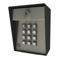
Identifies key parts of the keypad unit, including reset button and terminals.

Initial Unpacking and Mounting

Steps for carefully unpacking the unit and attaching it to a pedestal.

Critical Safety Warning

Alerts users to serious injury risks from automatic gates and the need for safety devices.

Wiring Diagrams for System Integration

Wiring for Gate Operator;Door Opener

Connects the keypad to a gate operator or door opener using power and relay terminals.

Wiring for Electric Strike

Connects the keypad to an electric door strike and exit device for access control.

Wiring for Magnetic Lock

Connects the keypad to a magnetic lock and exit device for secure access.

Access Code and Basic Programming

Add Access Codes to Relay A

Procedure to assign access codes that trigger Relay A for gate or door operation.

Manage Access Codes

Instructions for deleting existing access codes and changing the master code.

Set Latch Code

Configures a specific code to keep a relay activated until deactivated.

Programming Tips and Sub Modes

Explains keypad functions (Star/Pound keys) and lists available programming sub modes.

Advanced Programming and Configuration

Set Relay Output Time

Adjusts the duration (seconds) for which a relay remains active after code entry.

Add Access Codes to Relay B

Assigns access codes that trigger Relay B, typically for a second device.

Configure Event Input

Sets modes for external devices to control keypad operation or trigger relays.

Delete All Codes

Procedure to erase all stored access codes, returning the unit to a default state.

System Reset and Recovery Procedures

Master Reset Procedure

Restores the master code to default if forgotten, retaining other codes.

Unit Reset to Factory Defaults

Resets the entire unit to factory settings, erasing all codes and configurations.

Overview

The provided document is a Quick Start Guide for the ADVANTAGE DKE Model 26-500, a keypad unit designed for access control systems, primarily for gate operators, door openers, electric door strikes, and magnetic locks.

Function Description

The ADVANTAGE DKE Model 26-500 is a keypad-based access control system that allows users to enter a programmable access code to trigger a relay, thereby controlling a connected device such as a gate operator or door opener. It supports multiple access codes and offers various programming modes to customize its operation, including setting relay output times, configuring event inputs, and managing user codes. The unit is designed for outdoor installation, typically on a pedestal, and integrates with other security devices like exit devices and power sources.

Important Technical Specifications

The system operates with a power source of 12-24 VAC/DC. It features two independent relays (Relay A and Relay B), each with Normally Open (N/O), Normally Closed (N/C), and Common (COM) terminals, allowing for flexible wiring configurations with different types of access control devices. The keypad unit includes terminals for power, relay outputs, and event inputs. The event input terminals are used for wiring to an exit device, enabling external control over the keypad's operation or triggering a relay. The unit's programming allows for 4-digit access codes and offers a relay output time configurable from 000 to 999 seconds.

Usage Features

Installation:

  1. Unpacking: The first step involves carefully unpacking the box and verifying that all components are present, including the keypad unit, key, four carriage bolts, and four hex nuts.
  2. Mounting: The keypad unit's front panel is unlocked and removed. Using the provided carriage bolts and hex nuts, the unit is then attached to a pedestal. For ease of wiring, the front panel is inserted into the enclosure as shown in the diagrams.
  3. Wiring: The guide provides detailed wiring diagrams for various applications:
    • Gate Operator / Door Opener: Connects to the gate operator/door opener's terminals (POS. (+), NEG. (-), COM, RADIO, FREE EXIT, REVERSE LOOP, OPEN, STOP, CLOSE) and the keypad's power and relay terminals (POS. (+), NEG. (-), POWER, RELAY A, RELAY B). Relay B can be wired to a second device.
    • Electric Door Strike and Exit Device: Connects to a power source, an electric strike, and an exit device (e.g., 58-RTE-P). Earth ground is optional unless required by local code. The exit device connects to the Event Input Terminals on the keypad unit, while the electric strike connects to Relay A or B N/O and COM terminals.
    • Mag Lock and Exit Device: Similar to the electric door strike setup, but connects to a magnetic lock (e.g., 57-1200MAG) instead. The magnetic lock connects to Relay A or B N/C and COM terminals.

Programming: The system uses a Master Code (default: 1251) to enter programming mode. A "good" tone indicates a successful entry, while a "bad" tone signifies an incorrect entry. The Star Key (*) deletes the current entry, and the Pound Key (#) exits programming mode.

  • Add Access Code(s) to Relay A (Sub Mode 1): Master Code + 1 + Access Code(s) + # (4 digits, numbers only). Multiple codes can be entered before pressing the pound key.
  • Delete Code(s) (Sub Mode 2): Master Code + 2 + Code(s) to Be Deleted + # (4 digits, numbers only). Multiple codes can be deleted.
  • Change Master Code (Sub Mode 3): Current Master Code + 3 + New Master Code + # (4 digits, numbers only).
  • Set Latch Code (Relay A ONLY) (Sub Mode 5): Master Code + 5 + Latch Code + # (4 digits, numbers only).
  • Set Relay Output Time (Sub Mode 6): Master Code + 6 + Relay (1 for A, 2 for B) + Seconds (000-999) + #.
  • Add Access Code(s) to Relay B (Sub Mode 7): Master Code + 7 + Access Code(s) + # (4 digits, numbers only).
  • Configure Event Input (Sub Mode 9): Allows an external device to affect keypad operation or trigger a relay.
    • Modes:
      • Mode 1 - Remote Inactive Mode: Disables all Relay A codes when input is received.
      • Mode 2 - Arming Circuit Mode: Turns on keypad unit when input is received.
      • Mode 3 - Remote Open Mode: Triggers either Relay A or Relay B when input is received.
      • Mode 0 - Event Input Disabled: Disables event input.
    • Set Mode 1, Mode 2, Disable, or Check Current Mode: Master Code + 9 + Mode or Exit (0-2 or # to leave mode unchanged) + #. The unit beeps the mode number or makes no beep when disabled.
    • Set Mode 3 (Remote Open Mode): Master Code + 9 + 3 + Relay (1 for A, 2 for B) + #.
  • Delete All Codes (Sub Mode 0): Master Code + 0 + Master Code Again. This action cannot be undone and will sound a "good" tone when complete.

Maintenance Features

Reset Procedures: The guide outlines two reset procedures, emphasizing that an "error" tone will sound if a mistake is made, requiring the user to start over.

  • Master Reset: Used if the Master Code, Latch Code, or Sleep Code is unknown, or if the unit is in Latch Mode or Sleep Mode. Other codes are retained.

    1. Open front panel.
    2. Disconnect power (remove one power wire from screw terminal).
    3. Press and hold the Reset Button, reconnect power, then release the Reset Button (unit sounds one tone).
    4. Press the Star key (*) on the keypad three times.
    5. Close front panel. The Master Code is reset to default (1251).
  • Unit Reset: Resets the unit to factory default settings, erasing all codes.

    1. Open front panel.
    2. Disconnect power (remove one power wire from screw terminal).
    3. Press and hold the Reset Button, reconnect power, then release the Reset Button (unit sounds one tone).
    4. Enter Pound (#) Star (*) Pound (#) on the keypad (unit sounds "good" tone).
    5. Enter 1251 (Master Code) on the keypad (unit flashes status LEDs and beeps).
    6. While the unit is beeping, disconnect and reconnect power.
    7. Close front panel. The unit is reset to factory default settings.

Reset Button: The unit includes a dedicated Reset Button for performing these reset procedures.

Safety Warnings: The guide includes a prominent warning about automatic gates causing serious injury or death, advising users to always check that the gate path is clear and to use reversing or other safety devices.

Support: Contact information for technical support is provided: Call (972) 474-6390 or email techsupport@securitybrandsinc.com, available Monday-Friday, 8 am-5 pm Central.

Security Brands Advantage DKE Specifications

General IconGeneral
BrandSecurity Brands
ModelAdvantage DKE
CategoryKeypad
LanguageEnglish