Do you have a question about the SEFRAM SF6-36V2 and is the answer not in the manual?
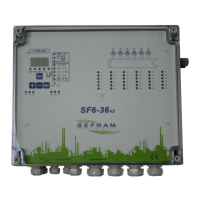
Details the SF6-36 V2 as a sequencer controller for dust-removal equipment with pressure measurement option.
Explains features like T1-T4 times, manual running, inputs, outputs, and DP thresholds.
States parameters are adjustable via front buttons and displayed on LED.
Clarifies that functions related to DP are only validated if the DP card is present.
Notes that S.V. output voltage and power output type are fixed at order and cannot be modified.
Details mains voltage, power consumption, solenoid valve voltage, and input characteristics.
Covers running/storage temperature, device protection (fuses, case material).
Lists parameters like max outputs, activation time (T1), idle time (T2/T2A), rest time (T3), cleaning time (T4).
Defines the DP scale, test pressure, and destructive pressure ratings.
Specifies fluid humidity, type, and materials in contact with fluids.
Details precision class, AP response time, alarm response times, and accelerated running thresholds.
Describes the 4-20mA output specifications, including supply and loading.
Illustrates the front panel layout with sections for signalling and settings.
Explains the various LEDs and their meanings on the front panel.
Identifies areas for sequencer parameter settings and S.V. output activation display.
Clarifies that DP measurement steps are inaccessible if the sensor is not present.
Details the process of setting parameters using SELECT, +, and - buttons.
Explains how parameters are saved and can be viewed during operation.
Describes the meaning of LED indications during operation and fault conditions.
Explains how DP measurements, faults, and cleaning cycles are displayed.
Explains choosing between 'AdP' (DP controlled) and 'SdP' (not DP controlled).
Defines thresholds for DP orders ('present'/'absent') and their behaviour.
Details setting high and low DP alarms and their activation conditions.
Explains setting the T2A threshold for accelerated operation and its effect on T2.
Describes cycle view indicators and options for stopping the cycle ('Fcy', 'Sto').
Refers to setting the number of paths/channels in the cleaning cycle.
Defines T1 as the activation time of an output in 1/100th of a second.
Defines T2 as the rest time between two outputs in seconds.
Defines T2A as the accelerated rest time between outputs (DP sensor required).
Defines T3 as the rest time between cycles in minutes.
Defines T4 as the maximum non-cleaning time in hours, used for scheduled cleaning.
Explains settings for fan stoppage cycles and manual running modes.
Describes how fan stop is detected (loss of input I3 or DP pressure drop).
Outlines conditions for cleaning start-up without a DP sensor (inputs I1, I2, I3).
Details start-up conditions with DP sensor (inputs I2, I3, DP order).
Explains how the sequencer handles fan stop detection via TOR input or pressure drop.
Describes the behaviour when input I2 (compressed air) is lost during operation.
Explains how to access the hidden menu by pressing Reset and Select buttons.
Covers setting DP detection modes ('PEt', 'PdP') and the stop fan detection value.
Describes how to view recorded DP high/low alarm values in the hidden menu.
Explains how to view the total number of cycles (thousands and units).
Details how to choose pneumatic control for SVs ('ACo' or 'ACn').
Explains the High alarm, Low alarm, and DEF (fault) LEDs.
Describes the DP LED (DP order present) and T2A LED (T2A time active).
Explains the LEDs indicating the status of inputs I1, I2, and I3.
Describes the LEDs for K1 (general fault), K2 (running response), and K3 (DP high alarm).
Lists and explains configuration fault codes (CF0 to CFb).
Details electrical fault codes for output supply and open circuits.
Explains fault codes related to compressed air control (climb, general, consumption).
Describes K1 relay operation for general faults, DP low alarm, and compressed air faults.
Explains K2 relay activation for sequencer running state and deactivation at stop.
Details K3 relay operation for DP high alarm status.
Defines I1 input for DP external loop control or T2A time with DP card.
Specifies I2 input for compressed air control.
Defines I3 input for fan loop control or other loop control.
Details the function of fuses F1, F2, F3, F4, F5, F6, F7, F8.
Lists fuse ratings for the 25VA/25W power supply version.
Lists fuse ratings for the 45VA/40W power supply version.
Explains jumper positions for mains voltage (115VAC/230VAC).
Details jumper settings for solenoid valve output voltages (24V, 48V).
Stresses the need to adapt fuses F3 and F4 when changing supply voltage.
Warns to update the manufacturing plate if supply or SV voltage is modified.
Advises making connections when de-energised and notes terminal availability.
Specifies cable conducting section (0.5 to 1.5 mm²).
Details connections for inputs I1, I2, and I3.
Explains connections for relay outputs K1, K2, K3.
Describes the 4-20mA output connection and its load.
Shows SV connection diagram using multiconductor cables.
Lists SV terminals (SV1 to SV36) and their common 'C' connections.
Illustrates SV connection diagram using separate cables for SV1 to SV24.
Shows SV terminals (SV1 to SV24) and their common 'C' connections.
Lists gland types and quantities for supply, inputs, outputs, and SVs.
Specifies connections for dirty air and clean air pressure tubes.
Provides fixing hole diameter and spacing for mounting the device.
Advises using identical fuses and shielded cables for 4-20mA.
Recommends avoiding dusty air at pressure taps and following device data.
Advises consulting for special conditions and using qualified staff for interventions.
States the device is factory adjusted for zero pressure and max pressure at 20°C.
Details the step-by-step procedure to adjust the zero pressure.
Lists available other supply voltages (24/48VAC, 24VDC).
Mentions availability of other DP sensor scales.
Emphasizes reading standards (NFC15-100), directives, and using qualified personnel.
Provides instructions for checking the device upon reception and storage conditions.
Details assembly operations, vertical mounting, cut-off devices, and PE connection.
Covers authorization for commissioning, personnel requirements, and conformity checks.
Advises on dust removal, avoiding dusty environments, and checking joints for maintenance.
Lists conditions under which the warranty is void (dropping, misuse, unauthorized intervention).
Instructs to return failed units to the specified address for action.
States compliance with Low Voltage and EMC directives.
Advises correct application and linking with CE approved products.
| Brand | SEFRAM |
|---|---|
| Model | SF6-36V2 |
| Category | Controller |
| Language | English |