SEG Electronics GmbH Manual MRG3
32 DOK-TD-MRG3, Rev. D
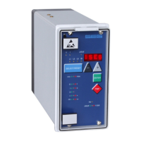
Figure 4.11: Phase position between the residual voltage and zero sequence current for faulted and non-faulted
lines in case of isolated systems (sin
)
U
E
-residual voltage
I
E
-zero sequence current
I
C
-capacitive component of zero sequence current
I
W
-resistive component of zero sequence current
By calculating the reactive current component (sin adjustment) and then comparing the phase
angle in relation to the residual voltage UE, the ER/XR-relay type determines whether the line to be
protected is earth-faulted.
On non-earth-faulted lines, the capacitive component Ic(a) of the total current precedes the residual
voltage by an angle of 90°. In case of a faulty line the capacity current IC(b) lags behind the residu-
al voltage at 90°.
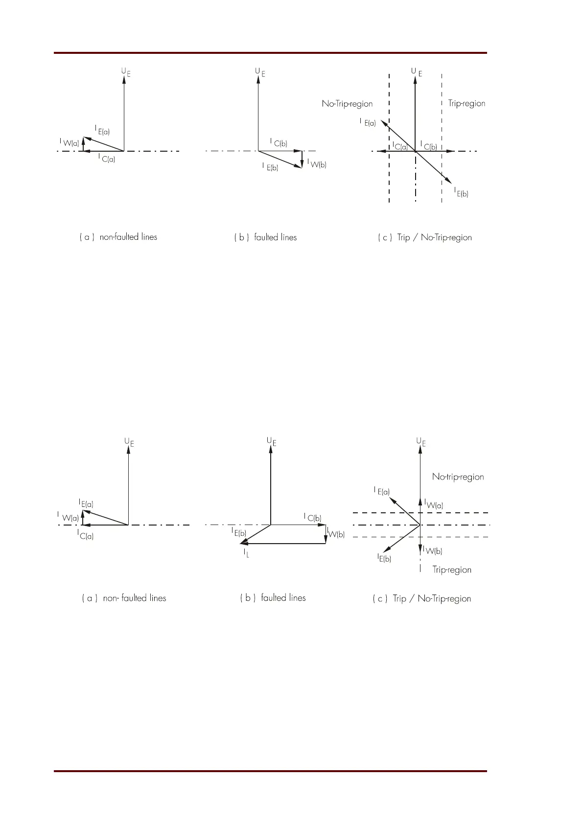
Figure 4.12: Phase position between the residual voltage and zero sequence current for faulted and non-faulted lines
in case of compensated systems (cos
)
U
E
residual voltage
I
E
zero sequence current
I
L
inductive component of zero sequence current (caused by Petersen coil)
I
C
capacitive component of zero sequence current
I
W
resistive component of zero sequence current