Do you have a question about the Sega MARIO & SONIC AT THE OLYMPICS GAMES TOKYO 2020 and is the answer not in the manual?
| Brand | Sega |
|---|---|
| Model | MARIO & SONIC AT THE OLYMPICS GAMES TOKYO 2020 |
| Category | Arcade Game Machines |
| Language | English |
Essential safety instructions and warnings for operating the product.
Checks to ensure the product is in satisfactory condition after transportation.
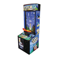
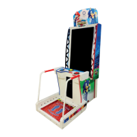
Technical details and dimensions of the game machine.
Clarifies who qualifies as site maintenance or other qualified professionals.
EU directive on disposal of electronic waste.
EC directive on battery disposal and recycling.
Information about product stickers, serial numbers, and contact details for repairs.
Details on warning labels for accident prevention and hazardous situations.
Warnings about risks of seizures and epilepsy from visual stimuli.
Ensures product compatibility with location's power supply, voltage, and frequency requirements.
Specifies minimum space requirements for safe operation and ventilation.
Checks for sufficient lighting, leg adjuster contact, and safe placement of items.
Guidelines for attendants to ensure player safety and prevent accidents during gameplay.
Step-by-step guide for installing the floor components of the machine.
Instructions for correctly installing the pipe assemblies.
Procedures for securing the floor joint cabi.
Steps for mounting the billboard and pop panel components.
Describes what happens when the machine is powered on.
Instructions for leveling and securing the machine at its installation location.
Guidance on safely connecting power and ground cables.
How to connect multiple cabinets for multiplayer setup using LAN cables.
Performing tests to confirm proper assembly and functionality of components.
Overview of the game's basic functionality and coin system.
Details the player's progression through the game, from coin insertion to event selection.
Explains the function of the test button, service button, and coin meter.
Navigating the main test mode menu and its sub-menus for testing.
Displays information about credits received and game play statistics.
Testing all input devices like buttons and foot sensors.
Testing output devices such as monitor LEDs and button lights.
Configuring game-specific settings like difficulty and price of play.
Technical specifications of the 55-inch Color TFT-LCD Module.
Guidelines for safely cleaning the LCD display screen.
Step-by-step instructions for removing the game buttons from the controller unit.
Procedures for cleaning the coin selector mechanism to ensure proper function.
Troubleshooting guide for common coin acceptor issues and their potential causes.
How to adjust the price of play using the EXCEL credit board settings.
Instructions for replacing the coin door lamp bulb.
Diagram showing the location and part numbers of LEDs.
Instructions for cleaning the cabinet surfaces and the LCD screen.
Steps to diagnose and resolve issues without error messages.
Detailed steps for safely removing the game board from the cabinet.
Explains the components and features of the game board.
Lists and explains common error codes displayed by the game board.
How to access and use the system test mode for various board functions.
Lists components for the Top Assembly.
Lists components for the Switch Unit Assembly.
Lists components for the Main Cabinet Assembly.
Lists components for the AC Unit Assembly.
Lists components for the Control Panel Assembly.
Lists components for the Floor & Base Assembly.
Lists components for the Left Hand Pipe Base Assembly.
Lists components for the Right Hand Pipe Base Assembly.
Lists components for the Left Hand Pipe Assembly.
Lists components for the Right Hand Pipe Assembly.
Lists components for the Floor Assembly.
Lists components for the Left Hand Foot Sensor Assembly.
Lists components for the Right Hand Foot Sensor Assembly.
Lists components for the Game Board Assembly.
Lists components for the Electrical Assembly.
Lists components for the LED Monitor Electrical Assembly.
Lists components for the Installation Kit Assembly.
Lists components for the Transformer Board Assembly.