Technical Guide
No. 9
No. PROCESS
ILLUSTRATIONS AND SPECIAL INSTRUCTIONS
Set the
POSITIONING PIN
B
20
Assemble the
DETECTION WHEEL
FOR YEAR
INDICATOR
19
Assemble the YEAR
INDICATOR WHEEL
18
Assemble the
YEAR
INDICATOR
DRIVING WHEEL
17
Assemble the
INTERMEDIATE
YEAR INDICATOR
WHEEL
16
Assemble the
DETECTION
WHEEL FOR
MONTH
INDICATOR
15
Assemble the
MONTH
INDICATOR
WHEEL
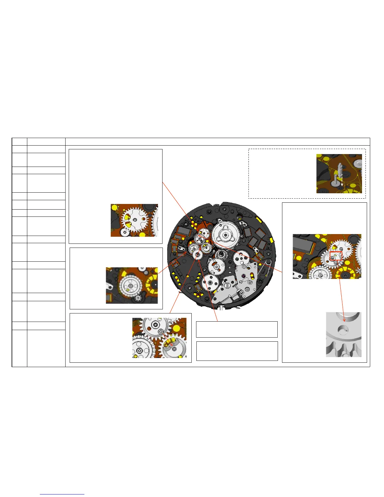
<15> Set the MONTH INDICATOR
WHEEL.
<17> Assemble the INTERMEDIATE
YEAR INDICATOR WHEEL.
Set the biggest hole of the wheel to
the positioning pin to correctly align
the wheel (see Fig. 9-4).
Check if its pinion is properly meshed
with the DETECTION WHEEL FOR
YEAR INDICATOR
(see Fig.9-5).
Set the POSITIOINING PIN B
Set the pin to the hole next
to the shaft for the
INTERMEDIATE YEAR
INDICATOR WHEEL
(see Fig.9-1).
Supporting pin
Fig. 9-1
<19> Assemble the
YEAR INDICATOR WHEEL.
Fig. 9-5
<16> Assemble the
DETECTION WHEEL
FOR MONTH INDICATOR.
Align the hole of the wheel
and the mark of the plate
(see Fig.9-6).
<20> Assemble the YEAR INDICATOR
DRIVING WHEEL.
Align the two detection holes of the wheel
and the two gilt cut BAUMKUCHEN
shaped detection patterns on the plate
(the position where the detection spring of
the wheel overlaps with the patterns) so
that the year detection works properly.
There are also
the alignment
marks in both the
wheel and the
plate to help your
easy alignment.
<18> Assemble the DETECTION WHEEL
FOR YEAR INDICATOR (see Fig.9-2).
Align the hole
of the wheel
and the gilt
dot mark of
the plate.
Fig. 9-6