The
mechanism
disposed
within
the
needle
bar is
detailed
on
Fig.
23A
which shows a needle bar in the operational state, while Fig. 23B shows a
needle
bar in
stopped
position.
The
force
of
spring
(1)
pushes
plunger
(2)
and
adjusting
nut
(3)
against
cone
(4)
which
in turn
forces
three
steel
balls
(5)
outwardly beyond the diameter of the needle bar and against the countersink
at the bottom end of the needle bar connecting stud (6). At the same time
triangular prism (18) is allowing three steel balls (7) to recede below the dia
meter
of
the
needle bar. Consequently,
the
movement
of
the
needle
bar
connecting
stud
will cause
the
needle
bar
to reciprocate.
When
stopping
a
needle
bar by
moving
the
change
over lever (1)
(Fig.
21) into
either
the
"L"
or
"R"
positions,
the
mechanism
locates
needle
bar
selector block
(8)—Fig.
23B—directly above the respective rod end (9). This
rod end of the reciprocating
needle
bar now contacts the selector
block
causing
the rod to move downward inside the needle bar causing cams (10 and 11) to
likewise move downward. This allows upper balls (19A) to recede below the
diameter of the needle bar while at the same time forcing lower balls (19B)
outwardly beyond the diameter of the needle bars. Lower balls (19B) are now
forced against the tapered mouth (14) of the needle bar bushing (13) and will
stop the downward movement of the needle bar. While needle bar position
guide (15) contacts the bottom of the upper end of the needle bar rock frame,
thereby locking the needle
bar
tightly into place.
At
the same time the retracted
upper balls
(1*9A)
do no longer lock the needle
bar
against the underside of
the needle bar connecting stud (6) and so allow the latter to glide along the
needle
bar.
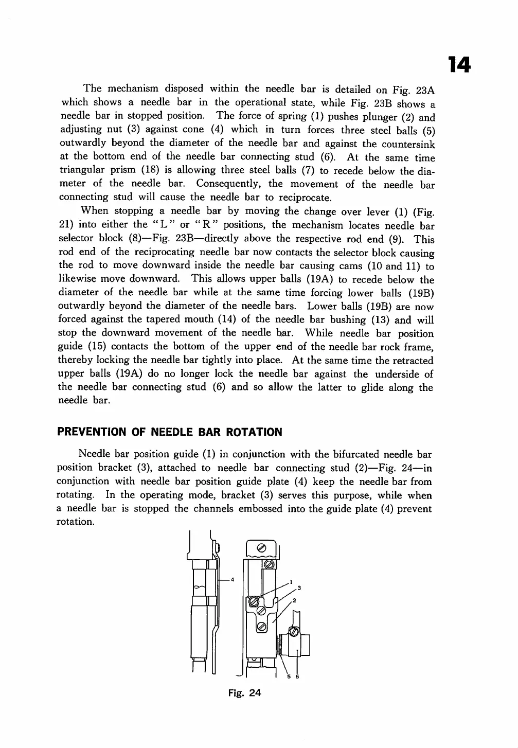
PREVENTION
OF
NEEDLE
BAR
ROTATION
Needle bar position guide (1) in conjunction with
the
bifurcated needle
bar
position bracket (3), attached to needle bar connecting stud (2)—Fig. 24—in
conjunction with needle bar position guide plate (4) keep the needle
bar
from
rotating. In the operating mode, bracket (3) serves this purpose, while
when
a needle
bar
is stopped the channels embossed into the guide plate (4) prevent
rotation.
n
Fig.
24
14
From the library of: Superior Sewing Machine & Supply LLC
 Loading...