SPECIAL
INSTRUCTIONS
FOR
MODEL
LTW-27BM
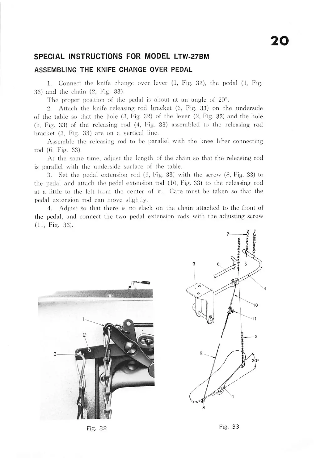
ASSEMBLING
THE
KNIFE
CHANGE
OVER
PEDAL
1. Connect the knife chantre over lever {1, Fig. 32), the pedal (1, Fig.
33)
and
the
chain
(2, Fig. 33).
The
proper position of the pedal is about at an angle of 20°.
2.
Attach
the
knife
releasing
rod
bracket
(3, Fig. 33) on
the
underside
of
the
table
.so
that the hole (3, Fig. 32) of the lever (2, Fig. 32)
and
the
hole
{5, Fig. 33) of the releasing rod (4, I'ig. 33) assembled to the releasing rod
bracket
(3, Fig. 33) are on a vertical line.
A.ssemble the releasing rod to be j)arallel with the knee lifter connecting
rod
(0, Fig. 33).
At
the
same time, adjust the length of the chain so that
the
releasing rod
is parallel with the underside surface of the table.
3.
Set
the
pedal
extension
rod (9, Fig. 33)
with
the
screw (8, Fig. 33) to
the pedal and attach the pedal extension rod (10, Fig. 33) to the releasing rod
at
a
little
to
the
left
fr{)m
the
center
of
it.
Care
must
be
taken
.so
that
the
pedal extension rod can move slightly.
4. Adjust so that there is no slack on the chain attached to the front of
the
pedal, and connect the two pedal extension rods with
the
adjusting screw
(11, Fig. 33).
Fig.
32
Fig.
33
20
From the library of: Superior Sewing Machine & Supply LLC
 Loading...