19
III.
Turn
hook
only
so
that
hook
point
comes
to
the
needle
as (7)—Fig. 29.
IV.
To
correctly adjust the position of
the
needles (1) relative to hook points
(2), remove the needle clamps (3) from their respective needle bars by
removing needle clamp
set
screw
(4).
Upon
removing
the
needle clamps,
needle clamp adjusting screw (5) become accessible.
Turn
adjusting
screw (5) either in or out to obtain the 4.4 mm (11/64") in LSW-27BLK
(4.1mm (5/32") in LTW-27BK) distance between the eye of the needle
when at its lowest position and
the
hook point (Fig. 29) after the needle
clamps with needles have been replaced on
the
needle bars.
Be sure
that
needle clamp adjusting screw (5) contacts
the
bottom
of needle
bar
plug (6) and tighten needle clamp set screws (4).
V.
Turn
hand
wheel toward you allowing needles to rise.
When
the
rotating
hook point crosses the centerline of the rising needle, it should be 2 mm
(5/64")
above the upper end of
the
eye of
the
needle. Adjust if
necessary. (Fig. 30)
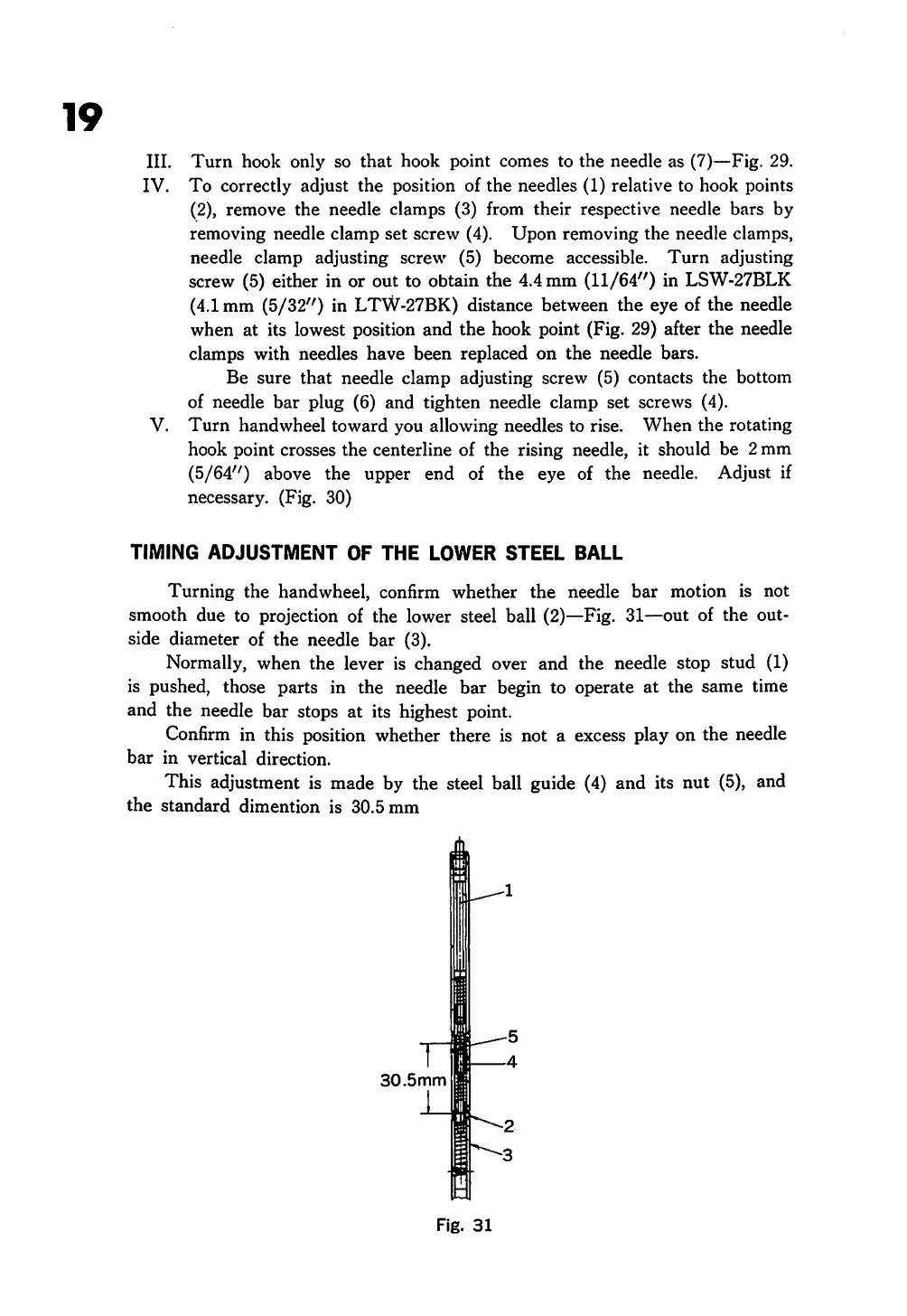
TIMING
ADJUSTMENT
OF
THE
LOWER
STEEL
BALL
Turning
the
hand
wheel, confirm whether
the
needle
bar
motion is not
smooth due to projection of the lower steel ball (2)—Fig. 31—out of the out
side diameter of the needle
bar
(3).
Normally, when the lever is changed over and the needle stop stud (1)
is pushed, those parts in the needle
bar
begin to operate at the same time
and the needle bar stops at its highest point.
Confirm in this position whether there is not a excess play on the needle
bar
in
vertical
direction.
This adjustment is made by the steel ball guide (4) and its nut (5), and
the
standard
dimention
is
30.5
mm
30.5mm
Fig.
31
From the library of: Superior Sewing Machine & Supply LLC
 Loading...