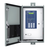
SEL-651RA Recloser Control Date Code 20160329
2
Step 2. Install the smaller ring terminal of the green/yellow ground
wire to the last connector screw and secure it with the last nut.
See Figure 1.
Step 3. Use the existing nut to connect the larger ring terminal of the
green/yellow ground wire to the ground stud. See Figure 1.
Step 4. If your unit is equipped with the fuse block for field wiring, go
to Wiring With Fuse Block. Otherwise go to Wiring Without
Fuse Block
Wiring Without Fuse
Block
Step 1. Form a drip loop and route the harness wires to the left toward
the 14-pin connector. See Figure 2.
Figure 2 Form Drip Loop and Route Harness Wires
Step 2. Join the 3-pin wires with the main harness and route the wires
through the wire loom and up the swing panel hinge through
the existing wire clamps.
Step 3. Route the wires across the top of the control module. The
accessory wires route separately from the main harness.
Step 4. Use the existing nuts to secure the wires to the top of the
control module with the two accessory wire clamps (if they are
not already installed). See Figure 3.
Figure 3 Secure Wires on Top of Control Module
Step 5. Attach the white wire from the 3-pin cable to the B26 terminal
on the control module and the black wire from the 3-pin cable
to B21 on the control module. See Figure 4.
Main Harness
Accessory Wires