Date Code 20160329 SEL-651RA Recloser Control
3
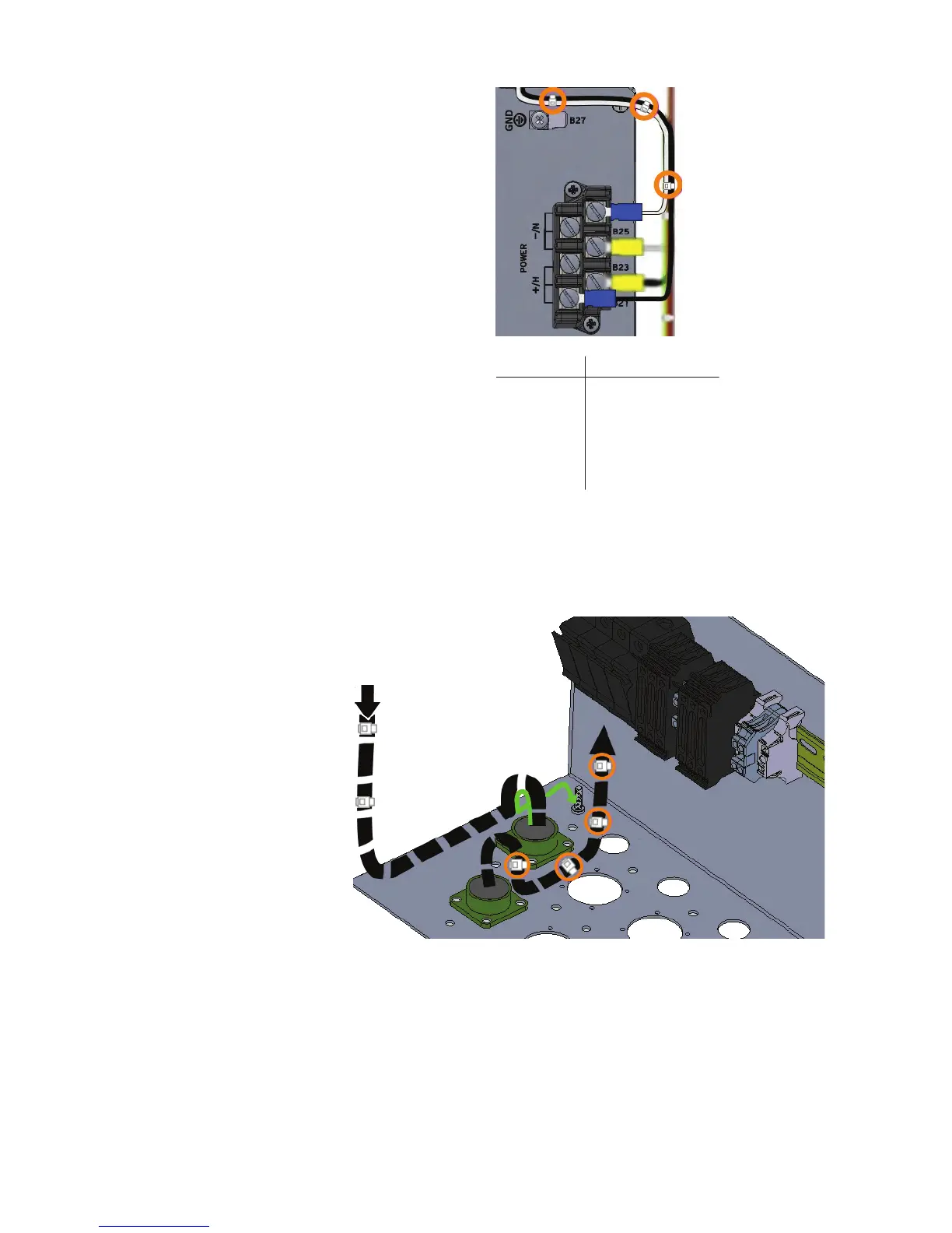
Figure 4 Attach Wires to Control Module
Step 6. Zip tie wires as necessary.
Wiring With Fuse
Block
Step 1. Form a drip loop and route the harness wires to the bottom of
the fuse block for field wiring. See Figure 5.
Figure 5 Route Harness Wires to Bottom of Fuse Block
Step 2. Cut the cables to a reasonable length and strip the individual
wires about 7/16 of an inch.
Step 3. Attach the white wire from the 3-pin cable to the N1 fuse on the
fuse block for field wiring and the black wire from the 3-pin
cable to the L1 fuse on the fuse block for field wiring. See
Figure 6.
3-Pin Wires: To:
A
B
C
B21
B26
A (Black Wire)
B (White Wire)
Ground Stud at
Bottom of Enclosure
(not shown)
C (Green and
Yellow Wire)