Home
Sel
Relays
SEL-351A
Page 64
Sel SEL-351A - Page 64
520 pages
Manual
Save Page as PDF
To Next Page
To Next Page
To Previous Page
To Previous Page
Loading...
3-10
Overcur
rent, Volt
age, Sync
hronis
m Check,
and Fr
equenc
y Element
s
Date Code
200103
07
SEL-351A I
nstruct
ion Manual
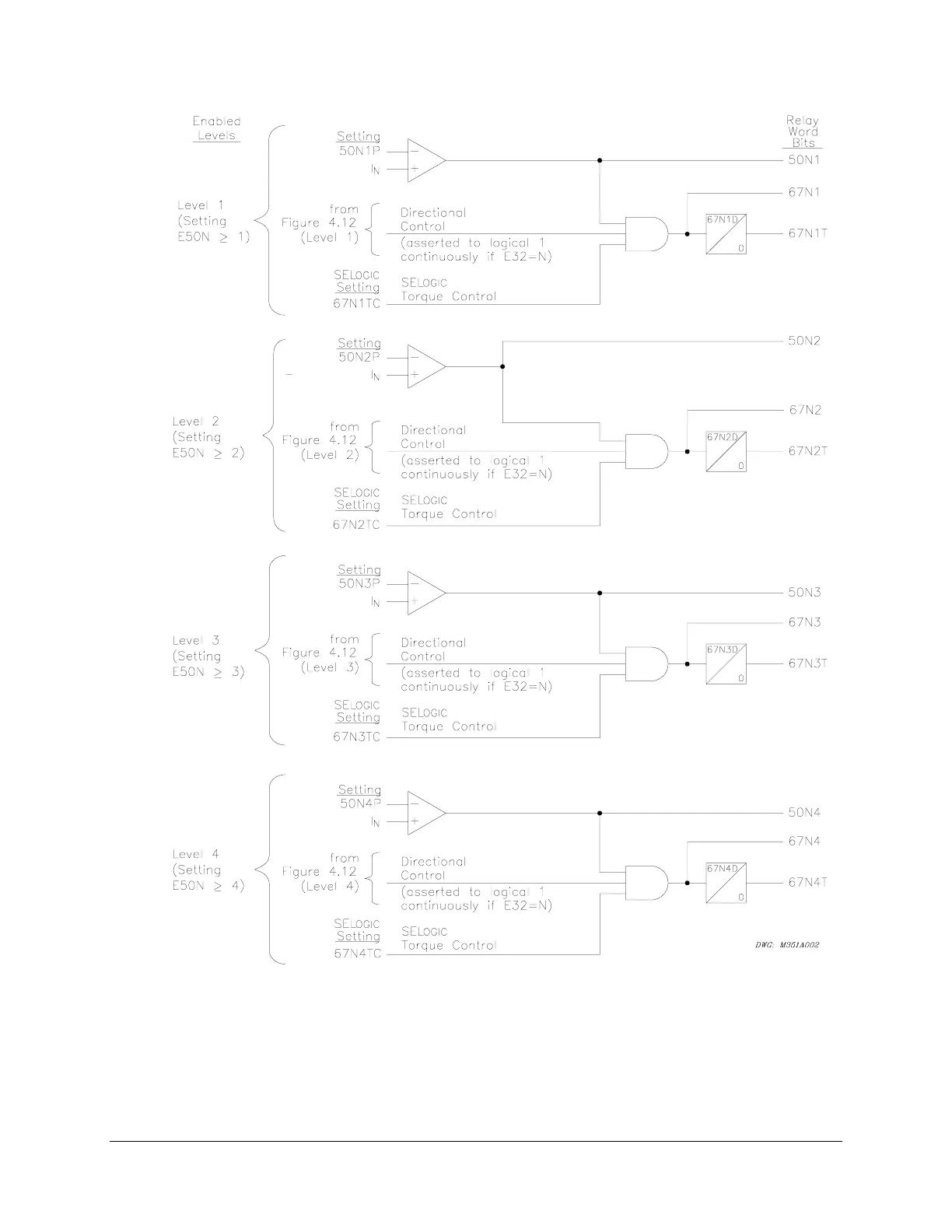
)LJXUH/
HYHOV7KU
RXJK1HXWU
DO*URXQG,QV
WDQWDQHRXV
'HILQL
WH7L
PH2YHU
FXUUHQW
(OHPHQWV:
LWK'LUH
FWLRQ
DO&RQWURO
2SWLRQ
63
65
Table of Contents
Main Page
Cover
1
MANUAL CHANGE INFORMATION
3
Table of Contents
7
Section 1: Introduction and Specifications
9
INTRODUCTION AND SPECIFICATIONS
11
SEL˚351A Relay Models
11
What’s the Difference Between the SEL˚351A Relay and the SEL˚351 Relay?
12
“Wire-Alike” Rear Panel Terminal Marking
12
Instruction Manual Sections
13
Applications
16
Hardware Connection Features
17
Communications Connections
18
General Specifications
19
Processing Specifications
22
Relay Element Pickup Ranges and Accuracies
23
Instantaneous/Definite-Time Overcurrent Elements
23
Time-Overcurrent Elements
23
Under- and Overvoltage Elements
24
Synchronism-Check Elements
24
Under- and Overfrequency Elements
24
Timers
24
Substation Battery Voltage Monitor
24
Metering Accuracy
25
Section 2: Installation
27
INSTALLATION
29
Relay Mounting
29
Rear-Panel Connection Diagram
30
Front-Panel Diagrams
31
Making Rear-Panel Connections
34
Screw-Terminal Blocks
34
Chassis Ground
34
Power Supply
34
Output Contacts
34
Optoisolated Inputs
34
Current Transformer Inputs
34
Potential Transformer Inputs
35
Serial Ports
35
IRIG˚B Time-Code Input
36
SEL˚351A Relay AC/DC Connection Diagrams for Various Applications
37
Circuit Board Connections
45
Accessing the Relay Circuit Boards
45
Output Contact Jumpers
47
“Extra Alarm” Output Contact Control Jumper
47
Password and Breaker Jumpers
48
EIA-232 Serial Port Voltage Jumpers
49
Condition of Acceptability for North American Product Safety Compliance
49
Clock Battery
50
Section 3: Overcurrent, Voltage, Synchronism Check, and Frequency Elements
51
OVERCURRENT, VOLTAGE, SYNCHRONISM CHECK, AND FREQUENCY ELEMENTS
55
Instantaneous/Definite-Time Overcurrent Elements
55
Phase Instantaneous/Definite-Time Overcurrent Elements
55
Settings Ranges
55
Accuracy
55
Pickup Operation
57
Directional Control Option
59
Torque Control
59
Combined Single-Phase Instantaneous Overcurrent Elements
60
Pickup and Reset Time Curves
61
Phase-to-Phase Instantaneous Overcurrent Elements
62
Setting Range
62
Accuracy
62
Pickup Operation
62
Pickup and Reset Time Curves
62
Neutral Ground Instantaneous/Definite-Time Overcurrent Elements
62
Settings Ranges
65
Accuracy
65
Pickup and Reset Time Curves
65
Residual Ground Instantaneous/Definite-Time Overcurrent Elements
65
Settings Ranges
67
Accuracy
67
Pickup and Reset Time Curves
67
Negative-Sequence Instantaneous/Definite-Time Overcurrent Elements
67
Settings Ranges
68
Accuracy
68
Pickup and Reset Time Curves
68
Time-Overcurrent Elements
70
Phase Time-Overcurrent Elements
70
Settings Ranges (51PT Element Example)
70
Accuracy
72
Logic Outputs (51PT Element Example)
72
Torque Control Switch Operation (51PT Element Example)
72
Torque Control Switch Closed
72
Torque Control Switch Open
73
Control of Logic Point TCP
73
Directional Control Option
74
Torque Control
74
Reset Timing Details (51PT Element Example)
75
Setting 51PRS = Y
75
Setting 51PRS = N
75
Operation of Single-Phase Time-Overcurrent Elements (51AT, 51BT, 51CT)
75
Neutral Ground Time-Overcurrent Element
77
Settings Ranges
78
Accuracy
78
Residual Ground Time-Overcurrent Element
78
Settings Ranges
79
Accuracy
80
Negative-Sequence Time-Overcurrent Element
80
Settings Ranges
81
Accuracy
81
Voltage Elements
82
Voltage Values
82
Voltage Element Settings
82
Accuracy
87
Voltage Element Operation
87
Undervoltage Element Operation Example
87
Overvoltage Element Operation Example
88
Synchronism Check Elements
88
Voltage Input VS Connected Phase-to-Phase or Beyond Delta-Wye Transformer
89
Synchronism Check Elements Settings
89
Setting SYNCP
89
Accuracy
90
Synchronism Check Elements Voltage Inputs
92
System Frequencies Determined from Voltages VA and VS
92
System Rotation Can Affect Setting SYNCP
92
Synchronism Check Elements Operation
93
Voltage Window
93
Other Uses for Voltage Window Elements
93
Block Synchronism Check Conditions
93
Slip Frequency Calculator
94
Angle Difference Calculator
94
Voltages VP and VS are “Static”
94
Voltages VP and VS are “Slipping”
95
Angle Difference Example (Voltages Vp and Vs are “Slipping”)
95
Synchronism Check Element Outputs
97
Voltages VP and VS are “Static” or Setting TCLOSD = 0.00
97
Voltages VP and VS are “Slipping” and Setting TCLOSD ( 0.00
97
Synchronism Check Applications for Automatic Reclosing and Manual Closing
99
Frequency Elements
99
Frequency Element Settings
99
Accuracy
101
Create Over- and Underfrequency Elements
101
Overfrequency Element
102
Underfrequency Element
102
Frequency Element Operation
102
Overfrequency Element Operation
102
Underfrequency Element Operation
103
Frequency Element Voltage Control
103
Other Uses for Undervoltage Element 27B81
103
Frequency Element Uses
103
Section 4: Loss-of-Potential, Load Encroachment, and Directional Element Logic
105
LOSS-OF-POTENTIAL, LOAD ENCROACH˜MENT, AND DIRECTIONAL ELEMENT LOGIC
107
Loss-of-Potential Logic
107
Setting ELOP = Y or Y1
108
Setting ELOP = Y
108
Setting ELOP = N
108
Load-Encroachment Logic
108
Settings Ranges
110
Load-Encroachment Setting Example
110
Convert Maximum Loads to Equivalent Secondary Impedances
110
Convert Power Factors to Equivalent Load Angles
111
Apply Load-Encroachment Logic to a Phase Time-Overcurrent
112
Use SEL-321 Relay Application Guide for the SEL-351A Relay
113
Directional Control for Neutral Ground and Residual Ground Overcurrent Elements
113
Internal Enables
115
Best Choice Ground Directional™ Logic
115
Directional Elements
115
Directional Element Routing
115
Loss-of-Potential
116
Direction Forward/Reverse Logic
116
Directional Control for Negative-Sequence and Phase Overcurrent Elements
124
Internal Enables
124
Directional Elements
125
Directional Element Routing
125
Loss-of-Potential
125
Direction Forward/Reverse Logic
126
Directional Control Settings
132
Settings Made Automatically
132
Settings
132
DIR1—Level 1 Overcurrent Element Direction Setting
132
DIR2—Level 2 Overcurrent Element Direction Setting
132
DIR3—Level 3 Overcurrent Element Direction Setting
133
DIR4—Level 4 Overcurrent Element Direction Setting
133
ORDER—Ground Directional Element Priority Setting
134
50P32P—Phase Directional Element Three-Phase Current Pickup
135
Z2F—Forward Directional Z2 Threshold
135
Z2R—Reverse Directional Z2 Threshold
135
Z2F and Z2R Set Automatically
135
50QFP—Forward Directional Negative-Sequence Current Pickup
136
50QRP—Reverse Directional Negative-Sequence Current Pickup
136
50QFP and 50QRP Set Automatically
136
a2—Positive-Sequence Current Restraint Factor, I2/I1
136
a2 Set Automatically
136
k2—Zero-Sequence Current Restraint Factor, I2/I0
137
k2 Set Automatically
137
50GFP—Forward Directional Residual Ground Current Pickup
138
50GRP—Reverse Directional Residual Ground Current Pickup
138
50GFP and 50GRP Set Automatically
138
a0—Positive-Sequence Current Restraint Factor, I0/I1
138
a0 Set Automatically
139
Z0F—Forward Directional Z0 Threshold
139
Z0R—Reverse Directional Z0 Threshold
139
Z0F and Z0R Set Automatically
139
E32IV—SELogic Control Equation Enable
139
Directional Control Provided by Torque Control Settings
140
Section 5: Trip and Target Logic
143
TRIP AND TARGET LOGIC
145
Trip Logic
145
Set Trip
146
Unlatch Trip
147
Other Applications for the Target Reset Function
148
Factory Settings Example (Using Setting TR)
148
Set Trip
148
Unlatch Trip
149
Additional Settings Examples
149
Unlatch Trip with 52a Circuit Breaker Auxiliary Contact
149
Unlatch Trip With 52b Circuit Breaker Auxiliary Contact
150
Program an Output Contact for Tripping
150
Switch-Onto-Fault (SOTF) Trip Logic
150
Three-Pole Open Logic
151
Determining Three-Pole Open Condition Without Circuit Breaker Auxiliary Contact
152
Circuit Breaker Operated Switch-Onto-Fault Logic
152
Close Bus Operated Switch-Onto-Fault Logic
152
Switch-Onto-Fault Logic Output (SOTFE)
153
Switch-Onto-Fault Trip Logic Trip Setting (TRSOTF)
153
Front-Panel Target LEDs
154
Additional Target LED Information
155
TRIP Target LED
155
INST Target LED
155
COMM Target LED
155
Another Application for the COMM Target LED
155
SOTF Target LED
156
50 Target LED
156
51 Target LED
156
81 Target LED
156
FAULT TYPE Target LEDs
156
A, B, and C Target LEDs
156
G Target LED
156
N Target LED
156
79 Target LEDs
157
Target Reset/Lamp Test Front-Panel Pushbutton
157
Other Applications for the Target Reset Function
157
SELogic Control Equation Setting FAULT
158
Section 6: Close and Reclose Logic
159
CLOSE AND RECLOSE LOGIC
161
Close Logic
161
Set Close
162
Unlatch Close
163
Factory Settings Example
163
Set Close
163
Unlatch Close
164
Defeat the Close Logic
164
Circuit Breaker Status
164
Program an Output Contact for Closing
165
Reclose Supervision Logic
165
Settings and General Operation
168
For Most Applications (Top of Figure 6.2)
168
For A Few, Unique Applications (Bottom of Figure 6.2 and Figure 6.3)
168
Set Reclose Supervision Logic (Bottom of Figure 6.2)
169
Unlatch Reclose Supervision Logic (Bottom of Figure 6.2)
169
Factory Settings Example
170
Additional Settings Example 1
170
SEL˚351A(1) Relay
171
SEL˚351A(2) Relay
171
Other Setting Considerations for SEL˚351A(1) and SEL˚351A(2) Relays
171
Additional Settings Example 2
172
Reclosing Relay
172
Reclosing Relay States and General Operation
173
Lockout State
173
Reclosing Relay States and Settings/Setting Group Changes
174
Defeat the Reclosing Relay
175
Close Logic Can Still Operate When the Reclosing Relay is Defeated
175
Reclosing Relay Timer Settings
175
Open Interval Timers
176
Determination of Number of Reclosures (Last Shot)
177
Observe Shot Counter Operation (only on models with LCD)
177
Reset Timer
177
Monitoring Open Interval and Reset Timing
178
Reclosing Relay Shot Counter
178
Reclosing Relay SELogic Control Equation Settings Overview
179
Reclose Initiate and Reclose Initiate Supervision Settings (79RI and 79RIS, respectively)
179
Factory Settings Example
179
Additional Settings Example
180
Other Settings Considerations
181
Drive-to-Lockout and Drive-to-Last Shot Settings (79DTL and 79DLS, respectively)
181
Factory Settings Example
182
Additional Settings Example 1
183
Additional Settings Example 2
183
Other Settings Considerations
183
Skip Shot and Stall Open Interval Timing Settings (79SKP and 79STL, respectively)
183
Factory Settings Example
184
Additional Settings Example 1
184
Additional Settings Example 2
185
Additional Settings Example 3
185
Other Settings Considerations
185
Block Reset Timing Setting (79BRS)
186
Factory Settings Example
186
Additional Settings Example 1
186
Additional Settings Example 2
187
Sequence Coordination Setting (79SEQ)
187
Factory Settings Example
187
Additional Settings Example 1
187
Additional Settings Example 2
190
Reclose Supervision Setting (79CLS)
191
Section 7: Inputs, Outputs, Timers, and Other Control Logic
193
INPUTS, OUTPUTS, TIMERS, AND OTHER CONTROL LOGIC
197
Optoisolated Inputs
197
Input Debounce Timers
198
Input Functions
199
Factory Settings Examples
199
Input IN101
199
Input IN102
200
Local Control Switches (only on models with LCD)
201
Local Control Switch Types
202
ON/OFF Switch
202
OFF/MOMENTARY Switch
202
ON/OFF/MOMENTARY Switch
203
Factory Settings Examples
204
Additional Local Control Switch Application Ideas
205
Local Control Switch States Retained
205
Power Loss
205
Settings Change or Active Setting Group Change
206
Remote Control Switches
206
Remote Bit Application Ideas
207
Remote Bit States Not Retained When Power is Lost
207
Remote Bit States Retained When Settings Changed or Active Setting Group Changed
207
Details on the Remote Control Switch MOMENTARY Position
207
Latch Control Switches
208
Latch Control Switch Application Ideas
209
Reclosing Relay Enable/Disable Setting Example
209
Feedback Control
210
Rising Edge Operators
211
Use a Remote Bit to Enable/Disable the Reclosing Relay
212
Latch Control Switch States Retained
212
Power Loss
212
Settings Change or Active Setting Group Change
213
Reset Latch Bits for Active Setting Group Change
213
Note: Make Latch Control Switch Settings With Care
214
Multiple Setting Groups
216
Active Setting Group Indication
216
Selecting the Active Setting Group
216
Operation of SELogic Control Equation Settings SS1 Through SS6
217
Operation of Serial Port GROUP Command and Front-Panel GROUP Pushbutton
217
Relay Disabled Momentarily During Active Setting Group Change
218
Active Setting Group Switching Example 1
218
Start Out in Setting Group 1
220
Switch to Setting Group 4
220
Switch Back to Setting Group 1
220
Active Setting Group Switching Example 2
221
Selector Switch Starts Out in Position 3
223
Selector Switch Switched to Position 5
223
Selector Switch Now Rests on Position REMOTE
223
Active Setting Group Retained
224
Power Loss
224
Settings Change
224
Note: Make Active Setting Group Switching Settings with Care
225
SELogic Control Equation Variables/Timers
225
Factory Settings Example
226
Additional Settings Example 1
227
Additional Settings Example 2
228
Timers Reset When Power is Lost, Settings are Changed, or Active Setting Group is Changed
228
Output Contacts
228
Factory Settings Example
229
Operation of Output Contacts for Different Output Contact Types
229
Output Contacts OUT101 Through OUT107
229
ALARM Output Contact
230
Rotating Default Display (only on models with LCD)
231
Traditional Indicating Panel Lights
232
Reclosing Relay Status Indication
232
Circuit Breaker Status Indication
232
Traditional Indicating Panel Lights Replaced with Rotating Default Display (only on models with LCD)
232
General Operation of Rotating Default Display Settings (only on models with LCD)
233
Factory Settings Examples
233
Reclosing Relay Status Indication
234
Reclosing Relay Enabled
234
Reclosing Relay Disabled
234
Circuit Breaker Status Indication
234
Circuit Breaker Closed
235
Circuit Breaker Open
235
Additional Settings Examples
235
Display Only One Message
235
Circuit Breaker Closed
235
Circuit Breaker Open
236
Continually Display a Message
236
Active Setting Group Switching Considerations
236
Setting Group 1 is the Active Setting Group
236
Reclosing Relay Enabled
237
Reclosing Relay Disabled
237
Switch to Setting Group 4 as the Active Setting Group
237
Additional Rotating Default Display Example
238
Displaying Time-Overcurrent Elements on the Rotating Default Display
238
Displaying Time-Overcurrent Elements Example
238
Displaying Metering Quantities on the Rotating Default Display
239
Displaying Metering Values Example
239
Displaying Breaker Monitor Output Information on the Rotating Default Display
240
Displaying Breaker Monitor Outputs Example
240
Section 8: Breaker Monitor and Metering
243
BREAKER MONITOR AND METERING
245
Introduction
245
Breaker Monitor
245
Breaker Monitor Setting Example
248
Breaker Maintenance Curve Details
248
Operation of SELogic Control Equation Breaker Monitor Initiation Setting BKMON
250
Breaker Monitor Operation Example
251
0 Percent to 10 Percent Breaker Wear
251
10 Percent to 25 Percent Breaker Wear
251
25 Percent to 50 Percent Breaker Wear
251
50 Percent to 100 Percent Breaker Wear
251
Breaker Monitor Output
256
Example Applications
256
View or Reset Breaker Monitor Information
256
Via Serial Port
256
Via Front Panel (only on models with LCD)
257
Determination of Relay Initiated Trips and Externally Initiated Trips
257
Factory Default Setting Example
257
Additional Example
258
Station DC Battery Monitor
259
DC Under- and Overvoltage Elements
259
Create Desired Logic for DC Under- and Overvoltage Alarming
260
DCLO < DCHI (Top of Figure 8.10)
260
DCLO > DCHI (Bottom of Figure 8.10)
261
Output Contact Type Considerations (“a” or “b”)
261
Additional Application
262
View Station DC Battery Voltage
262
Via Serial Port
262
Via Front Panel (only on models with LCD)
262
Analyze Station DC Battery Voltage
262
Station DC Battery Voltage Dips During Circuit Breaker Tripping
262
Station DC Battery Voltage Dips During Circuit Breaker Closing
263
Station DC Battery Voltage Dips Anytime
263
Operation of Station DC Battery Monitor When AC Voltage is Powering the Relay
263
Demand Metering
264
Comparison of Thermal and Rolling Demand Meters
264
Thermal Demand Meter Response (EDEM = THM)
266
Rolling Demand Meter Response (EDEM = ROL)
266
Time = 0 Minutes
267
Time = 5 Minutes
267
Time = 10 Minutes
268
Time = 15 Minutes
268
Demand Meter Settings
268
Demand Current Logic Output Application—Raise Pickup for Unbalance Current
269
Residual Ground Demand Current Below Pickup GDEMP
271
Residual Ground Demand Current Goes Above Pickup GDEMP
272
Residual Ground Demand Current Goes Below Pickup GDEMP Again
272
View or Reset Demand Metering Information
272
Via Serial Port
272
Via Front Panel (only on models with LCD)
273
Demand Metering Updating and Storage
273
Energy Metering
273
View or Reset Energy Metering Information
273
Via Serial Port
273
Via Front Panel (only on models with LCD)
273
Energy Metering Updating and Storage
273
Maximum/Minimum Metering
274
View or Reset Maximum/Minimum Metering Information
274
Via Serial Port
274
Via Front Panel
274
Maximum/Minimum Metering Update and Storage
275
Section 9: Setting the Relay
277
SETTING THE RELAY
279
Introduction
279
Settings Changes via the Front Panel (only on models with LCD)
279
Settings Changes via the Serial Port
279
Time-Overcurrent Curves
281
Relay Word Bits (Used in SELogic Control Equations)
285
Settings Explanations
306
Identifier Labels
306
Current Transformer Ratios
306
Line Settings
306
Enable Settings
307
Other System Parameters
307
Settings Sheets
307
Settings Sheet
309
Identifier Labels (See Settings Explanations in Section 9)
309
Current and Potential Transformer Ratios (See Settings Explanations in Section 9)
309
Line Settings (See Settings Explanations in Section 9)
309
Instantaneous/Definite-Time Overcurrent Enable Settings
309
Time-Overcurrent Enable Settings
309
Other Enable Settings
310
Phase Inst./Def.-Time Overcurrent Elements (See Figures 3.1, 3.2, and 3.3)
310
Phase Definite-Time Overcurrent Elements (See Figure 3.3)
310
Phase-to-Phase Instantaneous Overcurrent Elements (See Figure 3.7)
310
Neutral Ground Inst./Def.-Time Overcurrent Elements—Channel IN (See Figures 3.8 and€3.9)
311
Neutral Ground Definite-Time Overcurrent Elements (See Figure 3.8)
311
Residual Ground Inst./Def.-Time Overcurrent Elements (See Figures 3.10 and 3.11)
311
Residual Ground Definite-Time Overcurrent Elements (See Figure 3.10)
311
Negative-Sequence Inst./Def.-Time Overcurrent Elements (See Figures 3.12 and 3.13)*
312
Negative-Sequence Definite-Time Overcurrent Elements (See Figure 3.12)*
312
Phase Time-Overcurrent Element (See Figure 3.14)
312
A-Phase Time-Overcurrent Element (See Figure 3.15)
312
B-Phase Time-Overcurrent Element (See Figure 3.16)
312
C-Phase Time-Overcurrent Element (See Figure 3.17)
313
Neutral Ground Time-Overcurrent Element—Channel IN (See Figure 3.18)
313
Residual Ground Time-Overcurrent Element (See Figure 3.19)
313
Negative-Sequence Time-Overcurrent Element (See Figure 3.20)*
313
Load-Encroachment Elements (See Figure 4.2)
314
Directional Elements (See Directional Control Settings in Section 4)
314
Voltage Elements (See Figures 3.21, 3.22, and 3.23)
315
Synchronism Check Elements (See Figures 3.24 and 3.25)
316
Frequency Element (See Figures 3.27 and 3.28)
316
Reclosing Relay (See Tables 6.2 and 6.3)
316
Switch-Onto-Fault (See Figure 5.3)
317
Demand Metering Settings (See Figures 8.11 and 8.13)
317
Other Settings
317
SELogic Control Equation Variable Timers (See Figures 7.23 and 7.24)
317
Trip Logic Equations (See Figure 5.1)
319
Close Logic Equations (See Figure 6.1))
319
Reclosing Relay Equations (See Reclosing Relay in Section 6)
319
Latch Bits Set/Reset Equations (See Figure 7.13)
319
Torque Control Equations for Inst./Def.-Time Overcurrent Elements
320
Torque Control Equations for Time-Overcurrent Elements
321
SELogic Control Equation Variable Timer Input Equations (See Figures 7.23 and 7.24)
321
Output Contact Equations (See Figure 7.26)
322
Display Point Equations (only on models with LCD—See Rotating Default Display in Sections 7 and 11)
322
Setting Group Selection Equations (See Table 7.4)
322
Other Equations
323
Settings Group Change Delay (See Multiple Setting Groups in Section 7)
324
Power System Configuration and Date Format (See Settings Explanations in Section 9)
324
Front-Panel Display Operation (only on models with LCD—See Section 11)
324
Event Report Parameters (See Section 12)
324
Station DC Battery Monitor (See Figures 8.9 and 8.10)
324
Optoisolated Input Timers (See Figure 7.1)
324
Breaker Monitor Settings (See Breaker Monitor in Section 8)
324
Local Bit Labels (only on models with LCD—See Tables 7.1 and 7.2)
326
Display Point Labels (only on models with LCD—See Rotating Default Display in Sections 7 and 11)
328
Reclosing Relay Labels (See Functions Unique to the Front-Panel Interface in Section€11)
329
Protocol Settings (See Below)
330
Communications Settings
330
Other Port Settings (See Below)
330
Protocol Settings (See Below)
331
Communications Settings
331
Other Port Settings (See Below)
331
Protocol Settings (See Below)
332
Communications Settings
332
Other Port Settings (See Below)
332
Protocol Settings (See Below)
333
Communications Settings
333
Other Port Settings (See Below)
333
Section 10: Serial Port Communications and Commands
335
SERIAL PORT COMMUNICATIONS AND COMMANDS
337
Introduction
337
Port Connector and Communications Cables
337
IRIG-B
337
SEL˚351A to Computer
339
SEL˚351A to Modem
339
SEL˚351A to SEL˚PRTU
340
SEL˚351A to SEL˚2020 or SEL˚2030
340
SEL˚351A to SEL˚DTA2
340
Communications Protocol
341
Hardware Protocol
341
Software Protocols
341
SEL ASCII Protocol
342
SEL Distributed Port Switch Protocol (LMD)
343
SEL Fast Meter Protocol
343
SEL Compressed ASCII Protocol
343
Distributed Network Protocol (DNP) 3.00
343
Serial Port Automatic Messages
343
Serial Port Access Levels
344
Access Level 0
344
Access Level 1
345
Access Level B
345
Access Level 2
346
Command Summary
346
Command Explanations
348
Access Level 0 Commands
348
ACC, BAC, and 2AC Commands (go to Access Level 1, B, or 2)
348
Password Requirements
348
Access Level Attempt (Password Required)
348
Access Level Attempt (Password Not Required)
349
Access Level 1 Commands
350
BRE Command (Breaker Monitor Data)
350
DAT Command (View/Change Date)
350
EVE Command (Event Reports)
350
GRO Command (Display Active Setting Group Number)
351
HIS Command (Event Summaries/History)
351
IRI Command (Synchronize to IRIG-B Time Code)
352
MET Command (Metering Data)
353
MET k—Instantaneous Metering
353
MET X k—Extended Instantaneous Metering
354
MET D—Demand Metering
355
MET E—Energy Metering
356
MET M—Maximum/Minimum Metering
357
QUI Command (Quit Access Level)
357
SER Command (Sequential Events Recorder Report)
358
SHO Command (Show/View Settings)
358
STA Command (Relay Self-Test Status)
363
STA Command Row and Column Definitions
363
TAR Command (Display Relay Element Status)
364
TIM Command (View/Change Time)
366
TRI Command (Trigger Event Report)
366
Access Level B Commands
367
BRE n Command (Preload/Reset Breaker Wear)
367
CLO Command (Close Breaker)
367
GRO n Command (Change Active Setting Group)
368
OPE Command (Open Breaker)
369
PUL Command (Pulse Output Contact)
369
Access Level 2 Commands
370
CON Command (Control Remote Bit)
370
COP m n Command (Copy Setting Group)
370
PAS Command (View/Change Passwords)
371
SET Command (Change Settings)
372
VER Command (Show Relay Configuration and Firmware Version)
372
SEL-351A RELAY COMMAND SUMMARY
373
Section 11: Front-Panel Interface (only on models with LCD)
377
FRONT-PANEL INTERFACE (ONLY ON MODELS WITH LCD)
379
Introduction
379
Front-Panel Pushbutton Operation
379
Overview
379
Primary Functions
379
Front-Panel Password Security
380
Secondary Functions
381
Functions Unique to the Front-Panel Interface
383
Reclosing Relay Shot Counter Screen
383
Reclosing Relay Shot Counter Screen Operation (With Factory Settings)
384
Local Control
385
View Local Control (With Factory Settings)
386
Operate Local Control (With Factory Settings)
387
Local Control State Retained When Relay Deenergized
388
Rotating Default Display
389
Scroll Lock Control of Front-Panel LCD
391
Stop Scrolling (Lock)
392
Restart Scrolling (Unlock)
392
Single Step
392
Exit
392
Cancel
392
Front-Panel Neutral / Ground Current Display
392
Additional Rotating Default Display Example
393
Section 12: Standard Event Reports and SER
395
STANDARD EVENT REPORTS AND SER
397
Introduction
397
Standard 15/30-Cycle Event Reports
397
Event Report Length (Settings LER and PRE)
397
Standard Event Report Triggering
398
Relay Word Bit TRIP
398
Programmable SELogic Control Equation Setting ER
398
TRI (Trigger Event Report) and PUL (Pulse Output Contact) Commands
399
Standard Event Report Summary
399
Event Type
400
Fault Location
401
Targets
401
Currents
401
Retrieving Full-Length Standard Event Reports
401
Compressed ASCII Event Reports
402
Filtered and Unfiltered Event Reports
403
Clearing Standard Event Report Buffer
403
Standard Event Report Column Definitions
403
Current, Voltage, and Frequency Columns
404
Output, Input, and Protection, and Control Columns
404
Sequential Events Recorder (SER) Report
412
SER Triggering
412
Making SER Trigger Settings
413
Make Sequential Events Recorder (SER) Settings With Care
413
Retrieving SER Reports
413
Clearing SER Report
415
Example Standard 15-Cycle Event Report
415
Example Sequential Events Recorder (SER) Report
420
Section 13: Testing and Troubleshooting
423
TESTING AND TROUBLESHOOTING
425
Introduction
425
Testing Philosophy
425
Acceptance Testing
425
Commissioning Testing
425
Maintenance Testing
426
Testing Methods and Tools
427
Test Features Provided by the Relay
427
Low-Level Test Interface
427
Sensitive Earth Fault (SEF) Channel IN (0.05 A Nominal)
428
Test Methods
428
Testing Via Target Commands
429
Testing With the Front-Panel TAR Command (only on models with LCD)
429
Testing With the Serial Port TAR Command
429
Testing Via Output Contacts
429
Testing Via Sequential Events Recorder
429
Relay Self-Tests
430
Relay Troubleshooting
432
Inspection Procedure
432
Troubleshooting Procedure
432
All Front-Panel LEDs Dark
432
Cannot See Characters on Relay LCD Screen
433
Relay Does Not Respond to Commands From Device Connected to Serial Port
433
Relay Does Not Respond to Faults
433
Relay Calibration
433
Factory Assistance
433
Section 14: Appendices
435
APPENDIX A: FIRMWARE VERSIONS
439
Determining the Firmware Version in Your Relay
439
Firmware Revision History Table
439
APPENDIX B: FIRMWARE UPGRADE INSTRUCTIONS
441
Firmware (Flash) Upgrade Instructions
441
Important Note Regarding Settings
441
Required Equipment
441
Upgrade Procedure
441
APPENDIX C: SEL DISTRIBUTED PORT SWITCH PROTOCOL
447
Settings
447
Operation
447
APPENDIX D: CONFIGURATION, FAST METER, AND FAST OPERATE COMMANDS
449
Introduction
449
Message Lists
449
Binary Message List
449
ASCII Configuration Message List
449
Message Definitions
450
A5C0 Relay Definition Block
450
A5C1 Fast Meter Configuration Block
450
A5D1 Fast Meter Data Block
452
A5C2/A5C3 Demand/Peak Demand Fast Meter Configuration Messages
452
A5D2/A5D3 Demand/Peak Demand Fast Meter Message
454
A5B9 Fast Meter Status Acknowledge Message
455
A5CE Fast Operate Configuration Block
455
A5E0 Fast Operate Remote Bit Control
456
A5E3 Fast Operate Breaker Control
457
A5CD Fast Operate Reset Definition Block
457
A5ED Fast Operate Reset Command
458
ID Message
458
DNA Message
458
BNA Message
460
SNS Message
460
APPENDIX E: COMPRESSED ASCII COMMANDS
461
Introduction
461
CASCII Command—General Format
461
CASCII Command—SEL˚351A
462
CSTATUS Command—SEL˚351A
464
CHISTORY Command—SEL˚351A
464
CEVENT Command—SEL˚351A
465
APPENDIX F: SETTING NEGATIVE-SEQUENCE OVERCURRENT ELEMENTS
469
Setting Negative-Sequence Definite-Time Overcurrent Elements
469
Setting Negative-Sequence Time-Overcurrent Elements
469
Coordinating Negative-Sequence Overcurrent Elements
470
Coordination Guidelines
471
Coordination Example
471
Traditional Phase Coordination
472
Apply the Feeder Relay Negative-Sequence Overcurrent Element (Guidelines 1 to 3)
473
Convert “Equivalent” Phase Overcurrent Element Settings to Negative-Sequence€Overcurrent Element Settings (Guideline 4)
473
Negative-Sequence Overcurrent Element Applied at a Distribution Bus (Guideline 5)
474
Ground Coordination Concerns
475
Other Negative-Sequence Overcurrent Element References
475
APPENDIX G: SETTING SELogic® CONTROL EQUATIONS
477
Relay Word Bits
477
Relay Word Bit Operation Example—Phase Time-Overcurrent Element 51PT
477
Phase Time-Overcurrent Element 51PT Pickup Indication
477
Phase Time-Overcurrent Element 51PT Time-Out Indication
478
Phase Time-Overcurrent Element 51PT Reset Indication
478
Relay Word Bit Application Examples—Phase Time-Overcurrent Element 51PT
478
Other Relay Word Bits
479
SELogic Control Equations
479
SELogic Control Equation Operators
479
SELogic Control Equation Parentheses Operator ( )
480
SELogic Control Equation NOT Operator !
480
Example of NOT Operator ! Applied to Single Element
480
Example of NOT Operator ! Applied to Multiple Elements (Within Parentheses)
481
SELogic Control Equation Rising Edge Operator /
481
SELogic Control Equation Falling Edge Operator \
483
SELogic Control Equation Operation Example—Tripping
483
Analysis of SELogic Control Equation Trip Setting TR
484
Set an Output Contact for Tripping
485
All SELogic Control Equations Must Be Set
485
Set SELogic Control Equations Directly to 1 or 0
485
Set SELogic Control Equations Directly to 1 or 0—Example
485
SELogic Control Equation Limitations
486
Processing Order and Processing Interval
487
APPENDIX H: DISTRIBUTED NETWORK PROTOCOL (DNP) 3.00
489
Overview
489
Configuration
489
Data-Link Operation
490
Data Access Method
490
Device Profile
491
Object Table
493
Data Map
497
Relay Summary Event Data
500
Point Remapping
501
APPENDIX I: USING THE SEL 251 AND SEL 267 RELAY SETTINGS IN THE SEL 351A RELAY
505
Overview
505
Main Differences Between Settings on the SEL˚251, SEL˚267, and SEL˚351A Relays
505
Basic Protective Functions
505
Line Impedance Parameters
505
Phase Overcurrent and Time-Overcurrent Pickup Settings
506
Phase Time-Overcurrent Element Curve Settings
506
Residual Ground Overcurrent and Time-Overcurrent Pickup Settings
506
Residual Ground Time-Overcurrent Element Curve Settings
507
Negative-Sequence Overcurrent Pickup Settings
507
Negative-Sequence Time-Overcurrent Element Curve Settings
507
More Advanced Relay Functions
507
Undervoltage Elements (for the SEL˚251˚3 Relay Only)
507
Directional Elements (for the SEL˚267-5 Relay Only)
507
Torque Control
508
Reclosing Relay
508
Programmable Inputs and Outputs
508
Extra Features
508
Other Differences Between the SEL˚351A and the SEL˚251-3 and SEL˚267-5 Relays
508
Protective Functions
508
Reclosing Relay (79)
509
SELogic Control Equations
509
APPENDIX J: SEL-5030 acSELerator
511
Introduction
511
AcSELerator System Requirements
511
Installation
512
Starting AcSELerator
512
SEL-351A RELAY COMMAND SUMMARY
513
SEL-351A RELAY COMMAND SUMMARY
517
Related product manuals
Sel SEL-351S
758 pages
Sel SEL-300 Series
24 pages
Sel SEL-487E-3
36 pages
Sel SEL-787
612 pages
Sel SEL-751
6 pages
Sel SEL-849
6 pages
Sel SEL-751A
4 pages
Sel SEL-487B
32 pages
Sel SEL-2664S
16 pages
Sel SEL-487E-5
36 pages
Sel SEL-400 Series
24 pages
Sel 411L
1108 pages