Schweitzer Engineering Laboratories, Inc. SEL-411L Data Sheet
9
Each of the distance elements has a specific reach setting.
The ground distance elements include three zero-sequence
compensation factor settings (k01, k0R, and k0F) to cal-
culate ground fault impedance accurately. Setting k01
uses positive-sequence quantities to adjust zero-sequence
transmission line impedance for accurate measurement.
Settings k0F and k0R account for forward and reverse
zero-sequence mutual coupling between parallel trans-
mission lines.
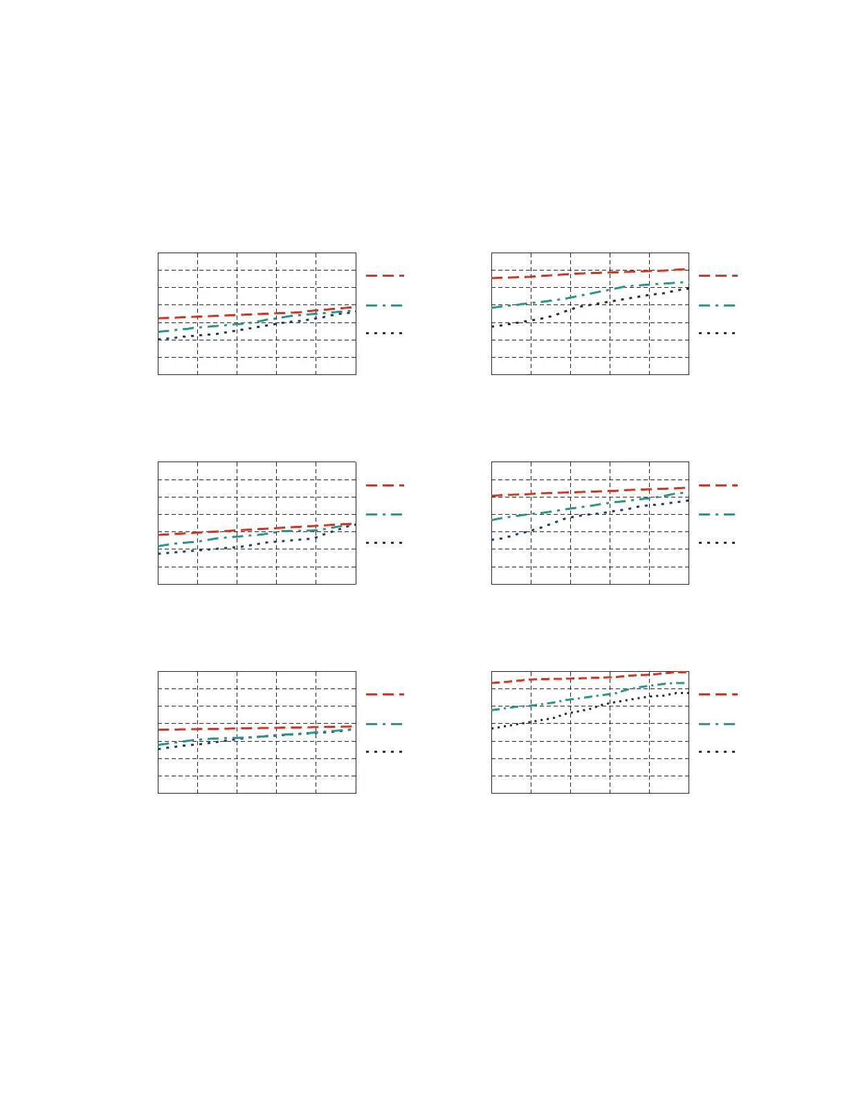
Figure 9–Figure 12 show the performance times of the
high-speed and standard distance elements for a range of
faults, locations, and source impedance ratios (SIR).
Subcycle Tripping Times Using Optional High-Speed Distance Elements
Figure 9 Mho Single-Phase-to-Ground Faults
Figure 10 Mho Phase-to-Phase Faults
Figure 11 Quadrilateral Single-Phase-to-Ground Faults
Fault Location as % of Reach Setting
0% 20% 40% 60% 80% 100%
Time in Cycles
Standard Speed Mho Ground Elements
0.25
0.50
0.75
1.25
1.50
1.0
1.75
0
SIR = 0.1
SIR = 1.0
SIR = 10.0
Fault Location as % of Reach Setting
0% 20% 40% 60% 80% 100%
Time in Cycles
High-Speed Mho Ground Elements
0.25
0.50
0.75
1.25
1.50
1.0
1.75
0
SIR = 0.1
SIR = 1.0
SIR = 10.0
Fault Location as % of Reach Setting
0% 20% 40% 60% 80% 100%
Time in Cycles
Standard Speed Mho Phase Elements
0.25
0.50
0.75
1.25
1.50
1.0
1.75
0
SIR = 0.1
SIR = 1.0
SIR = 10.0
Fault Location as % of Reach Setting
0% 20% 40% 60% 80% 100%
Time in Cycles
High-Speed Mho Phase Elements
0.25
0.50
0.75
1.25
1.50
1.0
1.75
0
SIR = 0.1
SIR = 1.0
SIR = 10.0
Fault Location as % of Reach Setting
0% 20% 40% 60% 80% 100%
Time in Cycles
Standard Speed Quad Ground Elements
0.25
0.50
0.75
1.25
1.50
1.0
1.75
0
SIR = 0.1
SIR = 1.0
SIR = 10.0
Fault Location as % of Reach Setting
0% 20% 40% 60% 80% 100%
Time in Cycles
High-Speed Quad Ground Elements
0.25
0.50
0.75
1.25
1.50
1.0
1.75
0
SIR = 0.1
SIR = 1.0
SIR = 10.0