29
www.selema.it
Service Manual
DC 4Q A Series
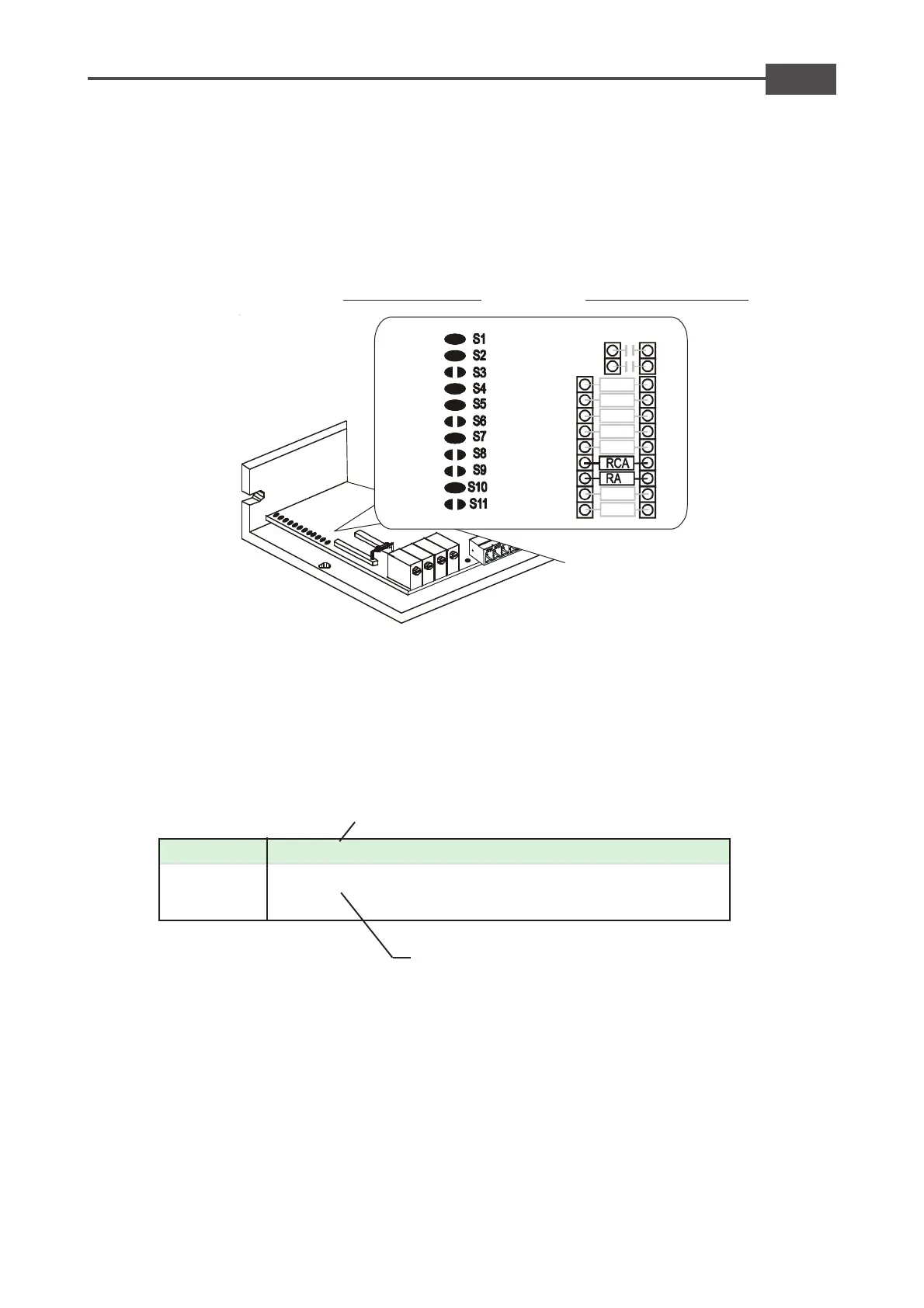
SOLDER BRIDGES
In this configuration, the drive must set with the following solder bridges and below internal setting:
Solder Bridges set for:
- Armature feedback
- Ramp time disabled
- Standard Dynamic constant
ADJUSTEMENT ZONE
Setting for Brush motor with armature
Note: On the adjustement zone are not considered
here the other components used to determine other
calibrations "for example. Calibration current rating
etc.".
RA 33 27 22 18 15 12 10 8,2 6,8 5,6 4,7 3,3
Model 65 59 53 47 42 37 31,5 28 24,5 21,5 19 16 13,5
Model100 92 82 74 65 58 50 44 38 34 29 26 21,5
RA resistor calculations
EXAMPLE: Brush DC motor with Ke= 26V/Krpm (Vdc)
Nominal speed N° =2000rpm
Risult: Vdc= 26*2000/1000= 52V
Drive model 65
Insert on base "RA" to adapt the system to use the motor voltage.
For the Example, risult Vdc=52V. The table shows a resistor with a value of 27Kohm.
Once the resistor RA is inserted, proceed with final speed adjustment.
Operate using trimmer SPEED on the front of the drive. With Clockwise Rotation the speed increases.
With Counter Clockwise Rotation the speed decreases. The Range of regulation is about +/- 25%.
Table Vdc voltage
Voltage output drive
Value of RA in Kohm