17. While the glue is drying, insert one plastic
bearing in each of the rubber hinges. Use your fin-
gers to slowly work the bearing to the center of
each rubber hinge tube. When all the glue is dry,
slide one of the flexible hinge tubes onto the strut
brace. Push it until the bearing seats against the
dowel. If the bearing does not touch the dowel, trim
a small amount off the end of the hinge tubing, re-
center the bearing and try again. Then insert the
hinge support into the other end of the tube until it
touches the bearing from the other side. Repeat
with the other 3 landing gears.
19. Now that the landing gears are assem-
bled and the glue is dry you may apply sanding
sealer to them. Apply sparingly to keep the weight
down. We recommend using Elmer's Fill and Finish
for sealing. You may apply it to all surfaces except
for the hinge and the hinge support. They must
remain unfilled and unpainted. After you apply the
sealer and sand the landing gears smooth you can
paint them. Paint the gear International Orange or
red. Paint the control cylinders and landing pads
silver.
18. After the glue has dried on the 4 landing
gears, make a glue fillet on all the strut brace joints
as shown it the illustration. Wipe it with your finger
making a fillet and allow the glue to set. Do the
same to both sides of the landing gear on the re-
maining three landing gears.
BREAK TIME!!
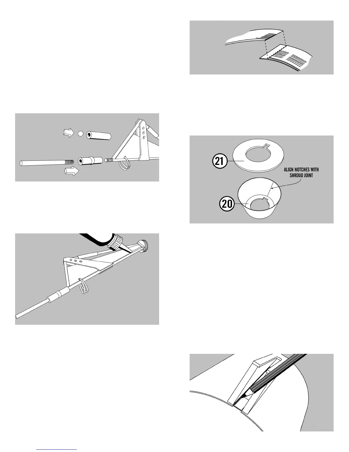
44. Set the small end of the engine shroud
down on a piece of wax paper. Insert the small noz-
zle spacing ring (20) and slide it down until it is
flush with the bottom of the shroud. Make sure the
engine hook notch is centered on the shroud joint.
Run a bead of glue around the ring shroud joint and
allow to dry.
45. Run a bead of glue around the inside of
the large opening in the shroud. Place the large
nozzle spacing ring (21) in the shroud and glue it
into place. Make sure that the engine hook notches
are in line with each other.
46. Next trim off the last 1/4” of each landing
gear opening in the descent body tube. Then slide
the entire landing gear assembly into the rear of the
descent stage. The aft bulkhead should be 1/16”
inward from the rear of the body tube. Align so
that the landing gears can move freely. Without
moving the bulkhead mark each exposed section of
the internal ring. The marks should be at the inside
edge of each gear housing. The landing gear are
not shown in the illustration below.
 Loading...