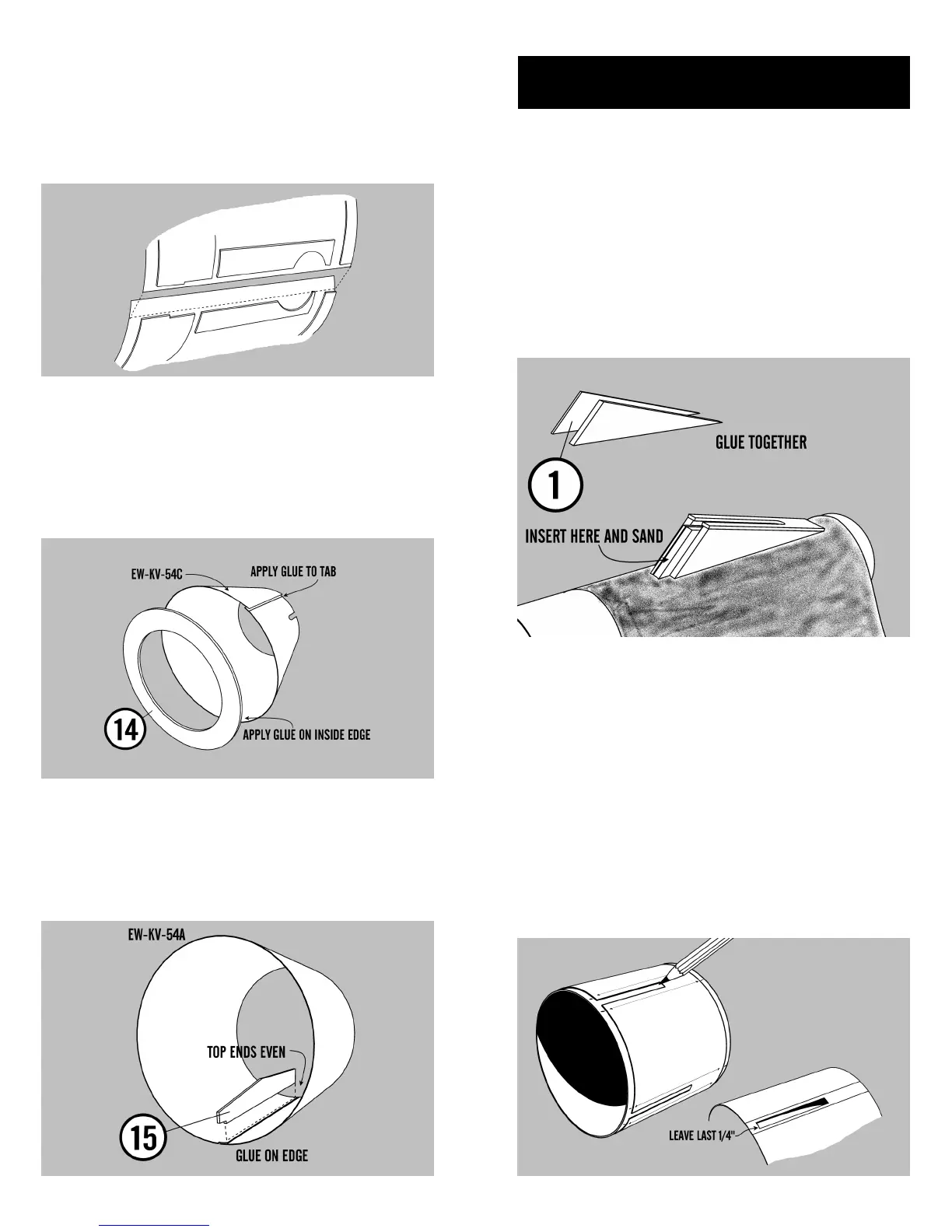
35. Glue the shroud together by applying
glue to the shroud tab and align the two sides to-
gether. Hold in place until it sets up and then leave
to dry. White glue works best for shrouds since it
does not shrink as much as some glues.
36. Follow the same procedure that you just
did in step 35 to the command module shroud. Af-
ter the glue has set for several minutes then press
the Command module bulkhead into the larger
opening and glue into place. Make sure the bulk-
head is even with the end of the shroud. Sanding
may be necessary to get the proper fit.
37. Punch out the notched ascent module
brace (15). Apply glue to the longest straight edge
and glue the brace to the shroud joint so that the
notched end is toward the large end of the shroud.
Hold in place until it sets and make sure it points
straight away from the shroud.
24. Punch out the balsa and paper (1) gear
housing spacers. Glue the two together and let dry.
Insert the spacer in between the groove in the gear
housing. Wrap a piece of sandpaper around the
chute tube (BT-60FG) and round the edges of the
gear housing by sanding them back and forth
against the tube. Do the same to the other three
housings. Make sure that the bottom edges of the
gear housings fit smoothly against the descent
stage tube (BT-100CE.) The spacer will be discarded
when you are finished with it.
MAIN ASSEMBLY
25. Cut out the descent stage marking guide.
Wrap the guide around the descent stage tube (BT-
100CE) and tape with masking tape. Center it over
the tube and mark the tube at each of the arrow
points. Draw a line on the tube around each of the
landing gear openings with a straight edge. Very
carefully cut out the landing gear openings in the
body tube except for the last 1/4” of the tube. The
tube will become very flexible and hard to work
with. Patience is required to avoid cutting through
the large tube. (Refer to illustration)