FLIGHT PREPPING
65. The Mars Lander™ is designed to fly with
B6-2, B4-2, and C6-3 engines only. Only fly your
Mars Lander™ in little or no wind. The Mars Lan-
der™ is marginally stable due to its short, squat
shape. Without an engine, the dry Center of Gravity
(CG) should be no more than 7.1” from the top of
the nose cone. That is about at the top of the gear
hub slots. Use two pencils to balance the Mars Lan-
der using the slots as fulcrum points. If the CG is
more than 7.1” from the nose cone tip, a small
amount of weight may be required in the nose cone
to make the Mars Lander™ stable.
68. Refer to the model rocket engine manu-
facturer’s instructions to complete the engine prep-
ping. Different engines have different igniters and
methods of hooking them up to the launch control-
lers.
69. Carefully check all parts of your rocket
before each flight as a part of your pre-flight check-
list. Launch the Mars Lander™ from a 1/8” diameter
by 36” long or longer launch rod. Aim the rod as
close to vertical as possible. The Mars Lander™ can
not recover from any angle of attack greater than
about 15 degrees. Any wind or flights off vertical
can result in unstable flights!
70. After each flight, remove the spent en-
gine casing and clean the model thoroughly for
many hours of fun flying with your Mars Lander™!
66. Pack the recovery wadding from the top
of the body tube. Use a sufficient quantity to protect
the parachute, but not too much that it will interfere
with the proper deployment of the parachute. For
best results, only push the recovery wadding down
far enough to allow room for the chute and cords.
67. Fold the parachute and pack it and the
shock cord on top of the recovery wadding. Slide
the nose cone into place, making sure it does not
pinch the shock cord or parachute. If you are flying
with a B4-2 or a B6-2 engine, the parachute must be
packed very loosely. Do not wrap the lines and
shock cord around the parachute or it will not have
time to unroll. The maximum altitude is only about
100 feet and a tightly rolled chute will take more
distance to unroll before impact.
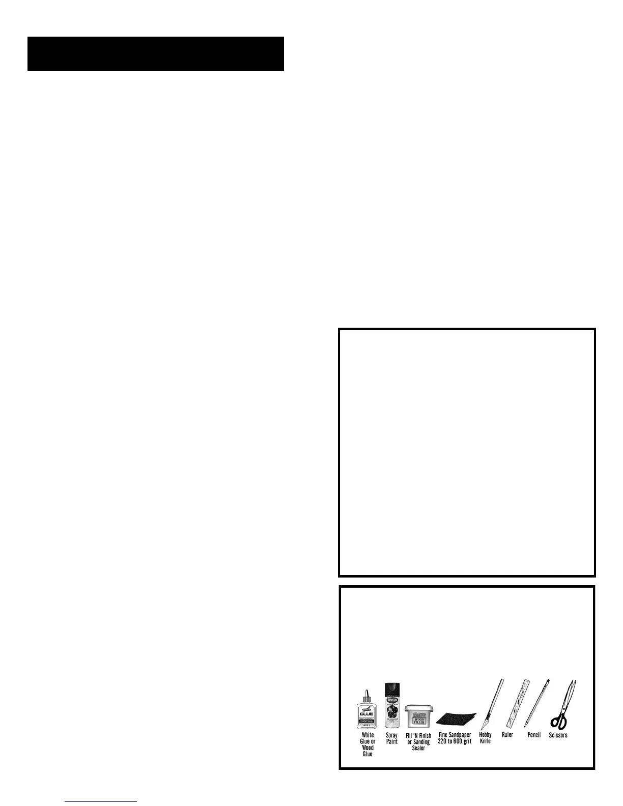
TOOLS: In addition to the parts supplied, you will
need the following tools to assemble and finish
this kit. You will also need masking tape, wax pa-
per, several straight pins, one round wooden
toothpick and paper towels for cleanup.
About the Mars Lander™
The Estes® Mars Lander was initially released in
1969. It was the first to use a functional shock ab-
sorbing landing gear. Following a trend to more
complex model rockets, the Mars Lander was de-
signed to challenge even more experienced model-
ers. Slow liftoff and low altitude made it ideal for
demonstration flights. The Mars Lander was intro-
duced as catalog #K-43 and had an introductory
price of $4.75.
The Semroc Mars Lander™ is a faithful recreation of
the original. It uses laser-cut balsa fins and laser-cut
fiber parts instead of the original die-cut parts. The
fiber is also thicker for sturdier construction. High
gloss embossed wraps are provided for authentic
looks of the original. A slightly larger chute is pro-
vided for longer life and a gentler recovery. A Kev-
lar® cord is provided for better shock cord reten-
tion.
BEFORE YOU START!
Make sure you have all the parts included in this kit
that are listed in the Parts List in the center of these
instructions. In addition to the parts included in this
kit, you will also need the tools and materials listed
below. Read the entire instructions before begin-
ning to assemble your rocket. When you are thor-
oughly familiar with these instructions, begin con-
struction. Read each step and study the accompa-
nying drawings. Check off each step as it is com-
pleted. In each step, test-fit the parts together be-
fore applying any glue. It is sometimes necessary
to sand lightly or build-up some parts to obtain a
precision fit. If you are uncertain of the location of
some parts, refer to the exploded view in the cen-
ter of these instructions. It is important that you
always ensure that you have adequate glue joints.
 Loading...