43. Form the engine nozzle shroud the same
as in step #34. Apply glue to the overhang and
press in position and hold until it sets. Then allow
the glue to dry.
40. Apply glue to the inside edge of the large
end of the ascent module shroud. Center the nar-
row bulkhead notch over the notched brace and
glue bulkhead in first with the ring facing out. Push
it into the assembly until it stops. DO NOT FORCE
IT! Make sure it is even all the way around the end
of the shroud.
41. Next pre-form the descent stage shroud
in the same way as before. Put glue on the tab and
press and hold into place until it sets then allow to
dry completely.
42. Put a piece of wax paper on a flat surface
and set the smaller end of the descent shroud on
the paper. Then slide the descent stage bulkhead
into the shroud until it is even with the bottom.
Glue the bulkhead into place.
20. Cut out the marking guide for the engine
mount from the pattern sheet provided. Wrap the
guide around the tube and center it. Using masking
tape to hold the guide in place, mark the tube at
each of the arrow points. After all marks are com-
plete, slide the marking guide off the tube. With a
straight edge draw a line passing over each mark
front and rear. On the letter (A) marks draw a line
down the entire length of the tube. This line will be
used to align the engine hook and several rings
later.
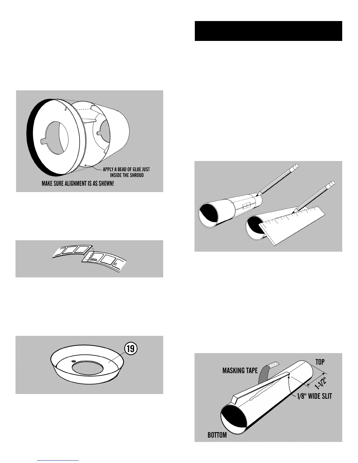
21. Cut a 1/8” wide slit in the engine tube on
the (A) line 1-1/2” from the top end. Insert the en-
gine hook into the slit and glue it in place centering
it over the (A) line. Only glue it up to 1” from the
slit. Hold the engine hook temporarily with mask-
ing tape until it dries.
ENGINE MOUNT