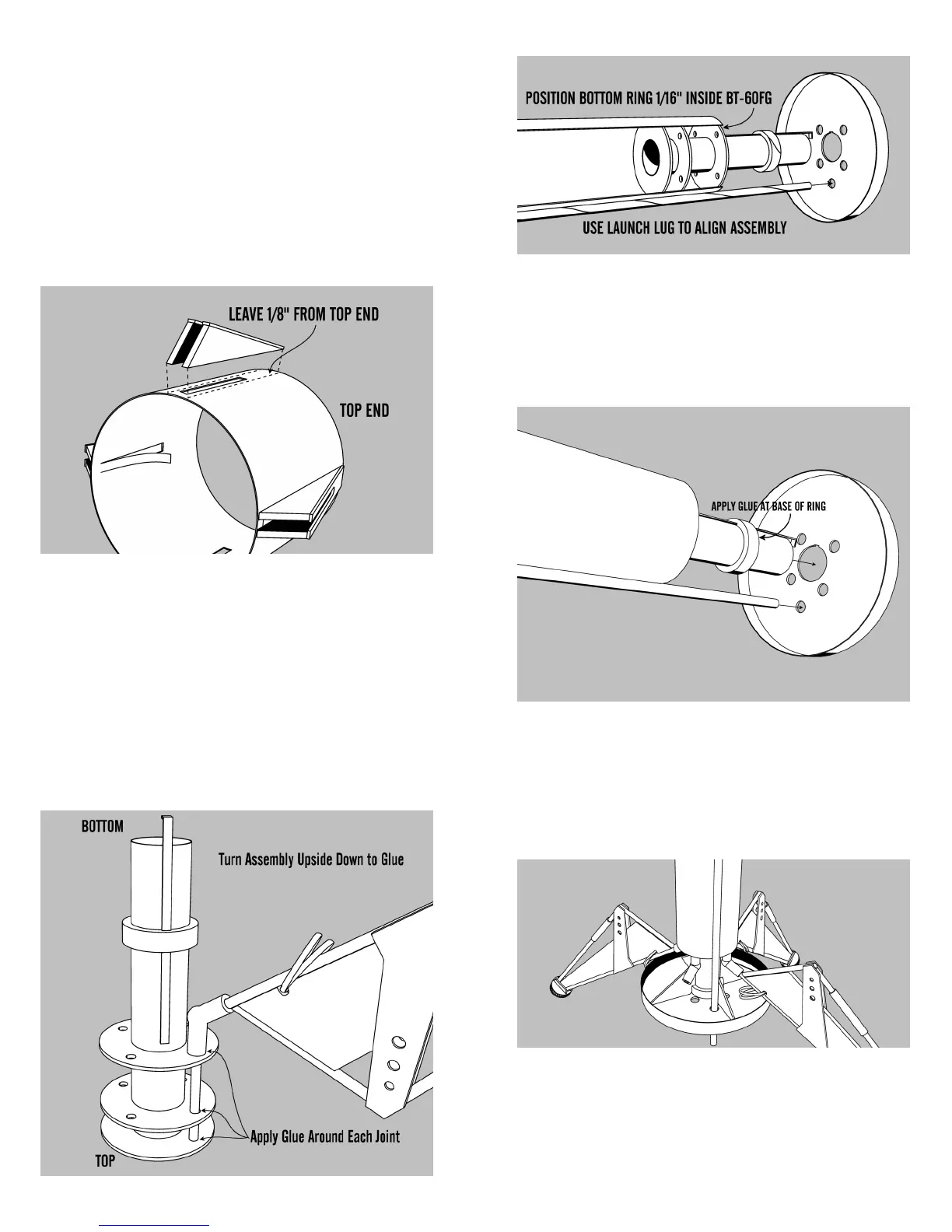
26. Next apply a line of glue along the two
longest edges of the gear housing as shown in the
illustration. Glue it to the body tube so that the
front of the housing is exactly 1/8” from the forward
end of the descent tube. Also make sure that the
sides of the housing are next to the alignment
marks that you put on the tube. Do the same to the
remaining three gear housings. Straight pins can be
used to temporarily hold the assemblies in place.
27. Next insert one of the landing gear as-
semblies into the matching holes in the ring. Posi-
tion the landing gear so that it points straight away
from the body tube. Make sure the end of the hinge
support dowel is touching the top ring (11). Apply a
glue fillet to each of the joints on the rings where
the landing gears come through. Glue the remain-
ing three assemblies in the same fashion. Refer to
the drawing below.
33. Punch out the Gussets (13) and apply a
line of glue to the bottom of one and the notch.
Glue the gusset in place in line with one of the
alignment lines that you drew on the tube earlier
Hold in place until it sets. Repeat with the other
three Gussets.
34. Pre-form the ascent module shroud by
carefully rolling into the approximate final shape.
You can use a pencil or dowel to help curl it into
shape, but the embossed surface is very fragile.
32. Apply a line of glue around the CR-79
ring and slide the aft bulkhead assembly onto the
engine mount tube. Make sure the internal ring
glued to the bulkhead is forward. Push the bulk-
head against the ring and allow to dry.