EN-6
WIRING DIAGRAM
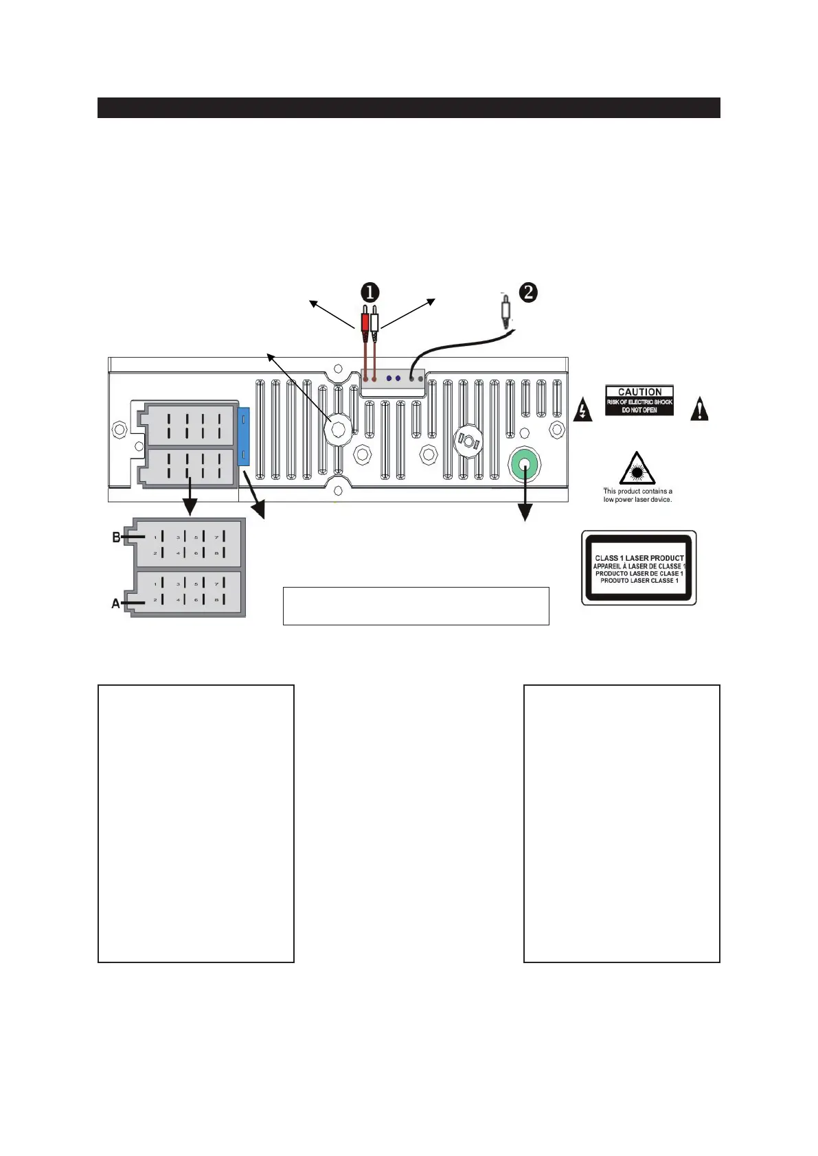
The Car Radio comes complete with built-in ISO connector and installation brackets and is easily fi tted into your car. Hereunder
you will fi nd the diagram of the ISO connection, which is used in the majority of the cars. If your vehicle is not fi tted with an ISO
connection, you can optionally purchase a female-ISO contra connector with separate wires and connect the wires according
the description of the ISO connector.
Note: Never connect cables to the system while it is connected to the battery power. Whenever the unit is disconnected from
the battery, the preset memory will be erased and the unit will go back to its factory defaults.
Right (Red) Left (White)
Subwoofer (Blue)
Fuse (15Amp.) ISO
ANTENNE
connection
1. Line OUTPUT Left + Right
2. Subwoofer
Note on ISO-A Connector: The pin layout
displayed here is the most commonly used,
but some car manufacturers (like VW, Audi,
Opel, Vauxhall) swap connection point A7
and A4, which results in Memory lost of
the preset channels and settings when the
ignition key is switched OFF. Please refer to
your car manual for correct connection of the
ISO connector in your car.
INTERNAL ISO CONNECTOR
ISO-A
A4
YELLOW B+. Always 12Vdc, direct
to battery.
A5
BLUE To system control terminal of
an external amplifi er or Automatic
Antenna (max. 100mA / 12V DC).
A7
RED ACC. Connect to the 12Vdc
controlled by the ignition key /
switch.
A8 GND. (Ground). Connect to clean,
exposed and unpainted metal parts
of the car chassis to make a good
ground connection.
ISO-B
FRONT SPEAKER
B3 Right + (Grey)
B4 Right – (Grey/Black)
B5 Left + (White)
B6 Left – (White/Black)
REAR SPEAKER
B1 Right + (Violet)
B2 Right – (Violet/Black)
B7 Left + (Green)
B8 Left – (Green/Black)