7
REF F-PRO-1725 (G)
• COMPONENTS
• See Figures 1.1 and 1.2
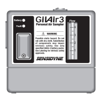
(1) Inlet Boss
The Inlet Boss is located on the filter housing and
provides a built-in means of attaching tubing for
suction sampling.
(2) Air Inlet Pump Filter
A 10 Micron Nylon Air Inlet Pump Filter protects
the pump assembly from dirt.
(3) Flow Adjustment (requires slotted screwdrivwer).
(4) Battery Check
This green LED (B) indicates that sufficient battery
power is available to run the pump for an 8 hour
period under normal load conditions.
(5) On/Off Switch
(6) Fault Indicator
This red LED (F) indicates a flow fault due to ex-
cessive pressure or insufficient battery voltage to
maintain flow.
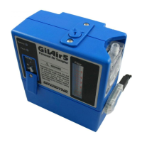
(7) Clock Display (DC Model only)
The Clock Display shows the continuous run-time
(in minutes, to two decimal places), and will lock-
in the sample time upon fault indication. The time
will reset to zero when the power switch is turned
OFF and then back ON again.
(8) Outlet Port
The Outlet Port provides a receptacle for the dis-
charge (bag sampling) boss accessory. The cap
screw prevents dirt from entering the Outlet Port
when not in use.
(9) Discharge (Bag Sampling) Boss
This is an accessory which, when installed into
the Outlet Port, provides a means for filling air
sampling bags.
(11)Charging Jack
The Charging Jack receptacle is used to connect
a charger for recharging the internal battery
pack.
(12)Belt Clip
(13)Rechargeable Battery Pack
(14)Tube Breaker Assembly.
(15)Mode Indicator
The Mode Indicator visually confirms the sam-
pling mode selected (via a Black/White indica-
tor)
(16)Mode Selector
The Mode Selector is used to change the sam-
pling mode. The selector is used for unlocking,
indexing, and re-locking the mode selector
valve while changing from Constant Flow Mode
to Constant Pressure (Multi-Flow) Mode.
(17)Hex Key
SECTION ONE
INTRODUCTION