MANUALE D'INSTALLAZIONE E USO
INSTALLATION AND USER MANUAL
MT3567rev2 13/12/2019 Page 11 of 18
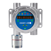
3.3 Scheda display per SMART S-SS
L’utilizzo del display è riportato nel relativo manuale (solo
per versione S-SS)
3.3 Display board for SMART S-SS
The use of the display is shown in the related manual
(only for S-SS version)
1
2
20
19
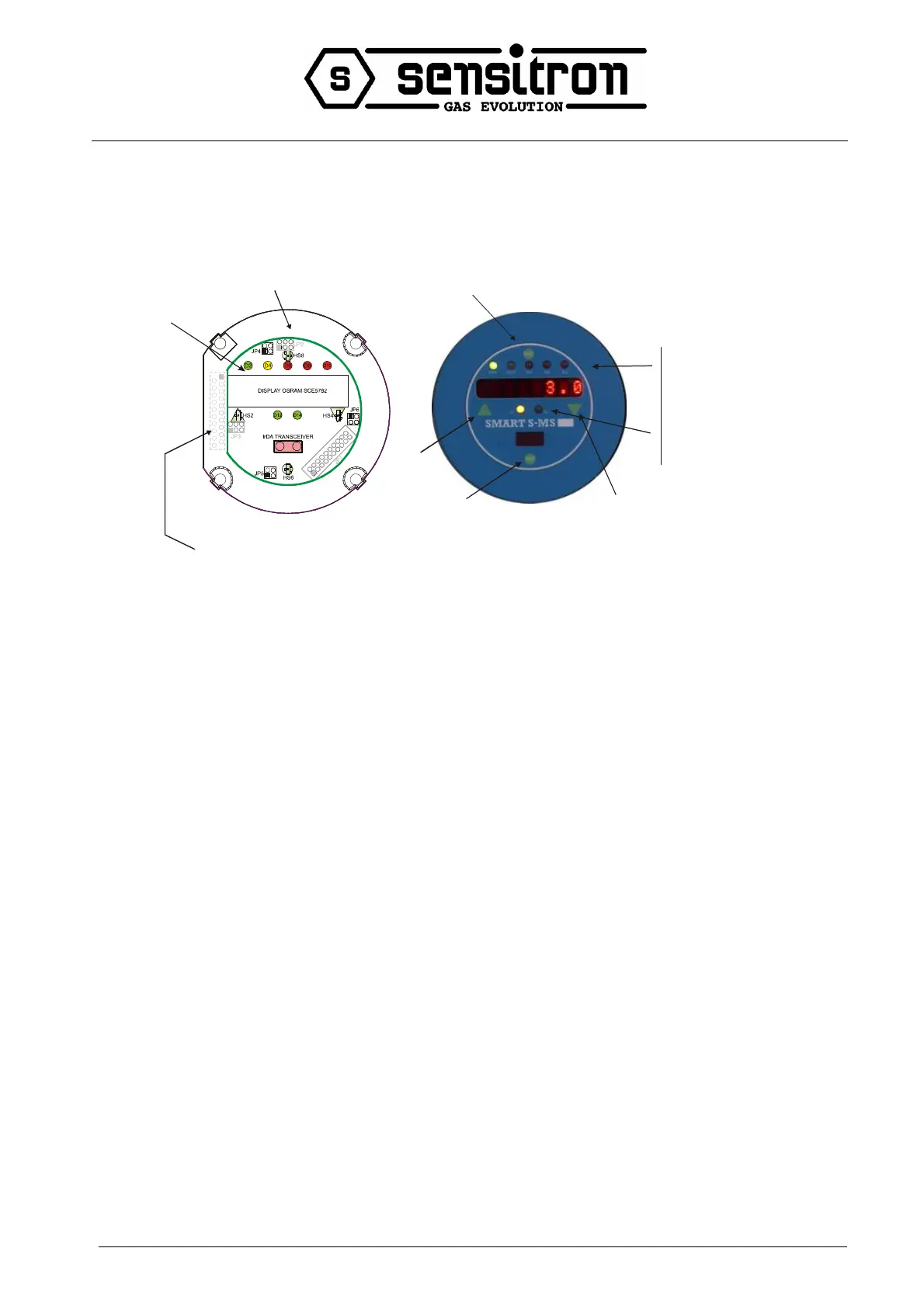
Connection to the detector
Main-Board (by special
cable).
Display mounting frame
Display board
Hs2, HS4, HS6 e HS8 :
Hall effect magnets for the detector
NON INTRUSIVE calibration.
HS2: Arrow UP
HS4: Arrow DOWN
HS6: ENT
HS8: ESC
LED indication:
D2: Power On (Green)
D4: Fault (Yellow)
D6: Alarm #1 (Red)
D8: Alarm #2 (Red)
D10: Alarm #3 (Red)
D12: Sensor #1 (Green)
D14: Sensor #2 (Green)
(if used)
Hs8
Hs2
Hs6
Hs4
3.4 Configurazione del rivelatore
3.4 Detector configuration
Il rilevatore dispone di una uscita proporzionale 4-20mA e
RS485.
The detector provides a 4-20mA proportional output and
RS485 serial output.
È possibile integrare nel rivelatore schede opzionali relè
ed Hart.
It is possible to provide relay and Hart boards.