www.sentera.eu
MIW-EVS-DM-EN-000 - 14 / 03 / 2016 15 - 16
back to the table of contents
■
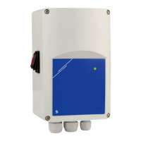
Input Register 14 (30014) shows the operating status of the unit. When the
register value is ‘0’ (Off), the controller is switched off. e ON/Stand-by LED on
the front panel is off. See Fig. 10 Operating indication.
When the value is ‘1’ (On), the controller operates according to the control
algorithm, and the analogue input signal is above the selected OFF level value (if
enabled). e ON/Stand-by LED (Fig. 10) gives out continuous light.
e ON / Stand-by LED blinks and the register value is 2 (Stand-by) when OFF level
is enabled and the analogue input signal is below the OFF level value.
HOLDING REGISTERS (See Table 1 Modbus register maps)
ese registers are read / write registers and they can be managed with “Read
Holding Registers” command, “Write single register” and “Write Multiple Registers”
commands. ey are organised in parts containing different kind of information.
e registers that are not used are read only. Writing on these registers does not
return Modbus error exception; however, it does not change anything either!
Part 1:
is part contains information about the unit and Modbus communication settings.
■
Holding register 1 (40001) contains the address at which the controller replies to
the Modbus master unit. e default address is ‘1’. You can change it in two ways:
1. Send command “Write Single Register” with address ‘1’ and write the new
address value.
2. Connect only your unit to a master controller or PC application and send the
command “Write Single Register” to address ‘0’ (Modbus broadcast address)
and write a new address value.
■
e next two registers (2 and 3) contain Modbus settings. Changing these
registers you change the communication settings. e default Modbus settings
are 19200-E-1 as it is stated in the Modbus Protocol Specification.
■
e next three registers (4, 5 and 6) are read only. ey contain information about
the hardware and firmware versions.
■
Holding register 7 (40007) sets the operation mode of the controller. ere are two
options: Standalone mode and Modbus mode. In Standalone mode the controller
is fully controlled by the analogue input signal and the selected hardware settings.
In Modbus mode the settings can be controlled by the Modbus master controller.
■
Holding register 8 (40008) is used for output override control. e setting is
used to override the output voltage by a preselected value. is value has greater
priority over the calculated output voltage of the integrated control algorithm.
Only kick start / soft start can change the output voltage value.
■
Holding registers 9 (40009) and 10 (40010) are not used. ey are read only.
Part 2:
■
Holding register 11 (40011) sets the analogue input signal type. e default value
is ‘1’ (0—10 VDC). ‘0’ is for 0—20 mA.
■
Holding register 12 (40012) defines the ascending / descending analogue input
mode. e default value is ‘1’ is for 0—10 VDC (ascending voltage signal). e
register values are ‘0’ for 10—0 VDC and ‘1’ for 0—10 VDC when voltage signal is
selected, and ‘0’ for 20— 0 mA and ‘1’ for 0—20 mA when current signal is selected
■
Holding register 13 (40013) contains the maximum output voltage. e default
value is ‘100’ (100 % Us or 230 VAC). e register values vary in the range of
75—100 (75—100 % Us).
■
Holding register 14 (40014) contains the minimum output voltage. e
default value is ‘30’ (30 % Us). e register values vary in the range of 30—70
(30—70 % Us).
■
Holding register 15 (40015) sets the OFF level state. e default value is ‘0’
(disabled). ‘1’ is for enabled.
EVS
ELECTRONIC FAN SPEED
POWER MODULE WITH MODBUS RTU
 Loading...