www.sentera.eu
MIW-EVS-DM-EN-000 - 14 / 03 / 2016 10 - 16
back to the table of contents
11. Close the enclosure and fix the cover.
12. Switch on the power supply.
13. Customise the factory settings to the desired ones, through 3SModbus
software (if necessary). For the default factory settings see Table Modbus
register maps.
VERIFICATION OF INSTALLATION INSTRUCTIONS
Follow the instructions below:
1. Switch on the mains supply.
2. Set the NBT jumper, DIP switch, Max. trimmer, Min. trimmer and OFF level
trimmer to desired positions / values. e factory settings are as follows:
►
NBT jumper is open (Network bus termination resistor is disconnected);
►
Ascending mode: 0—10 VDC / 0—20 mA
►
Off level - OFF;
►
Kick start disabled;
►
Input voltage mode (0—10 VDC);
►
Min. setting of the Min. speed trimmer
►
Max. setting of the Max. speed trimmer;
►
Min. setting of the Off level trimmer.
3. Set the analogue input signal to the maximum value of 10 VDC or 20 mA.
4. e connected motor will run at maximum speed or minimum speed depending
on the analogue input mode (ascending / descending).
5. If OFF level is enabled and descending analogue input mode is selected, the
motor will stop running.
6. Set the analogue input signal to the maximum value of 0 VDC or 0 mA.
7. e connected fan will run at minimum speed or maximum speed depending on
the analogue input mode (ascending / descending).
8. If OFF level is enabled and ascending analogue input mode is selected, the motor
will stop running.
9. If OFF level is enabled and the input signal is equal to the value of the OFF level,
the speed of the motor will be the minimum speed in ascending mode or the
maximum speed in descending mode.
10. If the controller does not work according to the instructions above, the wiring
connections and settings need to be checked.
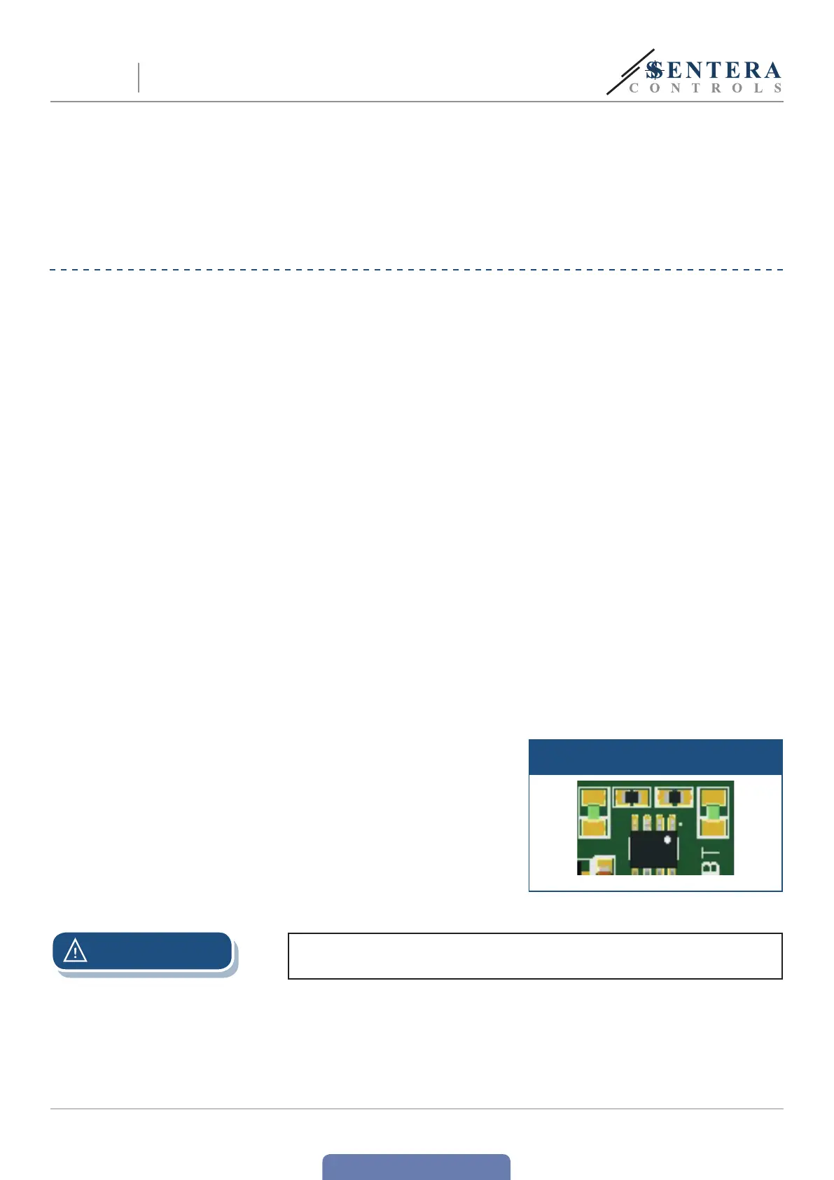
11. Check if both LEDs (Fig. 9) blink after you switch on your unit. If they do, your
unit has detected Modbus network. If they do not, check the connections again.
Fig. 9 Communication detection
indication
ATTENTION
e status of the LEDs can be checked only when the unit is energised. Take the
relevant safety measures!
EVS
ELECTRONIC FAN SPEED
POWER MODULE WITH MODBUS RTU
 Loading...