www.sentera.eu
MIW-EVS-DM-EN-000 - 14 / 03 / 2016 8 - 16
back to the table of contents
MOUNTING INSTRUCTIONS IN STEPS
Before you start mounting the EVS controller read carefully “Safety and
Precautions”. Choose a smooth surface for an installation location (a wall, panel
and etc.).
Follow these steps:
1. Switch off the power supply
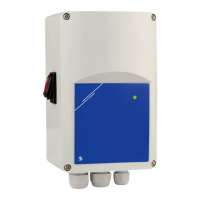
2. Open the enclosure cover and fix the unit to the wall or panel using the provided
dowels and screws. Mind the correct mounting position and unit dimensions.
(See Fig. 1 Mounting position and Fig. 2 Mounting dimensions.)
Fig. 1 Mounting dimensions Fig. 2 Mounting position
140
102
4,50
124
205
Acceptable Not acceptable
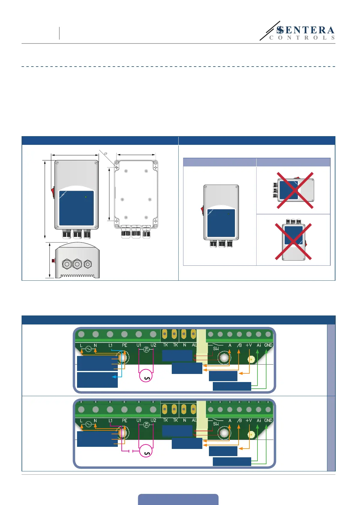
3. Connect the motor/fan.
4. Connect L1 output for a 3-wire connection, controlled valve, etc. (if necessary).
See Fig. 3b 3-wire motor connection.
Fig. 3 Wiring and connections
Power supply
230 VAC ,
50 / 60 Hz
Remote control
switch
Modbus RTU A
/B
Analogue input
0—10 VDC / 0—20 mA
Supply output
+12 VDC / 1 mA
L
N
PE
Unregulated
output
230 VAC / max. 2 A.
M
1
3a 2-wire motor connection
Power supply
230 VAC,
50 / 60 Hz
Remote control
switch
Modbus RTU A
/B
Analogue input
0—10 VDC / 0—20 mA
Supply output
+12 VDC / 1 mA
L
N
PE
M
1
3b 3-wire motor connection
EVS
ELECTRONIC FAN SPEED
POWER MODULE WITH MODBUS RTU
 Loading...