www.sentera.eu
MIW-EVS-DM-EN-000 - 14 / 03 / 2016 9 - 16
back to the table of contents
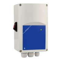
5. Select the required analogue input type and mode, start mode and OFF level
mode by the DIP switch on the board. (See Fig. 4 DIP switch settings.)
Fig. 4 DIP switch settings
Ascending/descending mode
selection
(DIP switch, position 1)
ON
1 2 3 4
ON - Descending mode:
10—0 VDC/20—0 mA
OFF - Ascending mode:
0—10 VDC/0—20 mA
OFF level selection
(DIP switch, position 2)
ON
1 2 3 4
ON - enabled
OFF - disabled
Kick start / soft start selection
(DIP switch, position 3)
ON
1 2 3 4
ON - Kick start
OFF - Soft start
Input mode selection
(DIP switch, position 4)
ON
1 2 3 4
ON - Current mode
(0—20 mA)
OFF - Voltage mode
(0—10 V DC )
6. Check if your unit starts or terminates the network (see Example 1 and
Example 2). If it does, put the NBT jumper onto the pins. If it does not, leave
the jumper open (see Fig. 5).
Example 1 Example 2
Fig. 5 Network bus
resistor jumper
Slave 1
RX
ТX
NBT
NBT
NBT
Slave 2
Master
Slave n
Slave 2
Slave 1
ТX
NBT
NBT
Master
Slave n
ATTENTION
If an AC power supply is used with any of the units in a Modbus network, the
GND terminal should NOT BE CONNECTED to other units on the network or
via the CNVT-USB-RS485 converter. is may cause permanent damage to the
communication semiconductors and/or the computer!
7. Connect the power supply cable.
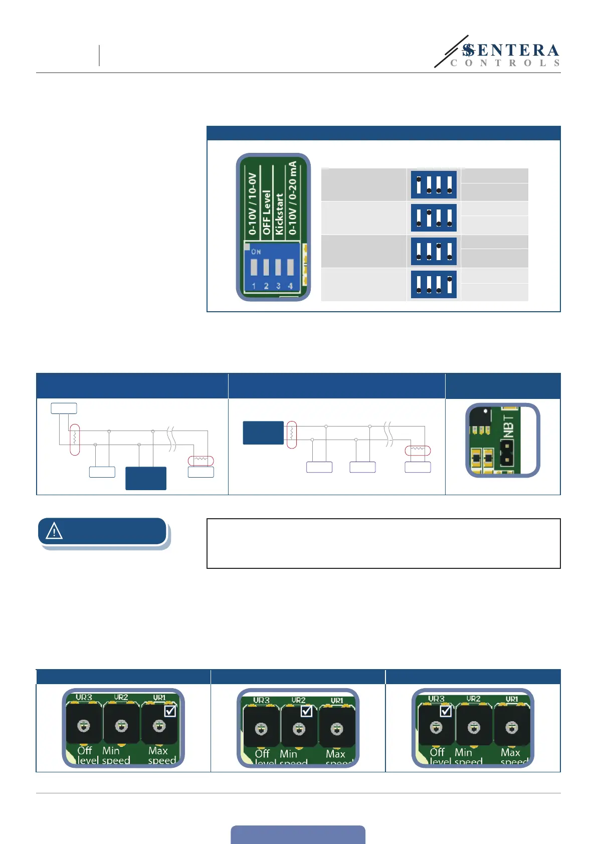
8. Adjust the max. speed by trimmer (if necessary). e default setting is Us
(230 VAC). See Fig. 6 Max. speed trimmer.
9. Adjust the min. speed by trimmer (if necessary). e default setting is 30 % Us
(69 VAC). See Fig. 7 Min. speed trimmer.
10. Adjust the OFF level value by trimmer (if necessary). e default setting is
0 VAC. See Fig. 8 Off level trimmer.
Fig. 6 Max. speedtrimmer Fig. 7 Min. speed trimmer Fig. 8 Off leveltrimmer
EVS
ELECTRONIC FAN SPEED
POWER MODULE WITH MODBUS RTU
 Loading...