Page 7 of 8
Doc 6001051, Rev C
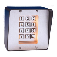
REMOTE KEYPAD
You may install a remote keypad to work with the Mini-Key. All information programmed into the Mini-Key will be the
same information read by the remote keypad (refer to the manual titled "PROGRAMMING AND USE
INSTRUCTIONS FOR THE MINI-KEY SYSTEM" for more information). Please Note: Run cables in metal conduit
(not PVC) and ground them. Do not run power and data wires in the same conduit. Do not connect the power to
the Mini-Key system until all connections have been made.
1. Install a remote keypad according to Figure 11.
2. Connect the shields to the ground screw on the Mini-Key.
7
6
5
4
3
2
1
Remote Keypad
Power Connections
Lighted
Remote Keypad
Data Connections
J2
2 / 18 AWG
Ground
Splice near
Mini-Key Unit
12V AC/DC
PWR IN
7 / 20-24 AWG
EXT KYPD
TB4
TB2
PINS
1 2 3 4 5 6 7
TB1
1051F9
Power Source
Figure 11: Installing a Remote Keypad
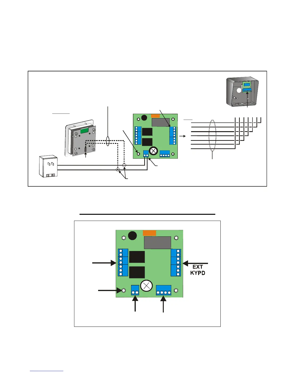
Reference: Main Processor Board
COM1
NC1
NO1
COM2
NC2
NO2
7
6
5
4
3
2
1
EXIT1, EXIT2, TZONE, COM
TB1 TB2
TB4
TB3
GROUND
12V AC/DC
PWR IN
1051F5
Figure 12: Mini-Key Main Processor Board