Introduction
1. The control valve, fittings and/or bypass are
designed to accommodate minor plumbing mis-
alignments but are not designed to support the
weight of a system or the plumbing.
2. Do not use Vaseline, oils, other hydrocarbon lubri-
cants or spray silicone anywhere. A silicon lubri-
cant may be used on black o-rings but is not nec-
essary. Avoid any type of lubricants, includ-
ing silicone, on red or clear lip seals.
3. The nuts and caps are designed to be unscrewed
or tightened by hand or with the special plastic
wrench. If necessary pliers can be used to
unscrew the nut or cap. Do not use a pipe wrench
to tighten or loosen nuts or caps. Do not place
screwdriver in slots on caps and/or tap with a
hammer.
4. Do not use pipe dope or other sealants on threads.
Teflon tape must be used on the threads of the 1”
NPT elbow or the 1/4” NPT connection and on the
threads for the drain line connection. Teflon tape
is not necessary on the nut connection or caps
because of o-ring seals.
5. After completing any valve maintenance involving
the drive assembly or the drive cap assembly and
pistons, press and hold NEXT and REGEN but-
tons for 3 seconds or unplug power source jack
from the printed circuit board (black wire) and
plug back in. This resets the electronics and
establishes the service piston position. The dis-
play should flash all wording, then flash the soft-
ware version (e.g. 154) and then reset the valve to
the service position.
6. All plumbing should be done in accordance with
local plumbing codes. The pipe size for the drain
line should be a minimum of 1/2”. Backwash flow
rates in excess of 7 gpm or length in excess of 20’
require 3/4” drain line.
7. Solder joints near the drain must be done prior to
connecting the drain line flow control fitting.
Leave at least 6” between the drain line control
fitting and solder joints when soldering pipes that
are connected on the drain line control fitting.
Failure to do this could cause interior damage to
the drain line flow control fitting.
8. When assembling the installation fitting package
(inlet and outlet), connect the fitting to the
plumbing system first and then attach the nut,
split ring and o-ring. Heat from soldering or sol-
vent cements may damage the nut, split ring or o-
ring. Solder joints should be cool and solvent
cements should be set before installing the nut,
split ring and o-ring. Avoid getting primer and
solvent cement on any part of the o-rings, split
rings, bypass valve or control valve.
9. Plug into an electrical outlet. Note: All electrical
connections must be connected according to local
codes. (Be certain the outlet is uninterrupted.)
10. Install grounding strap on metal pipes.
Page 4
General Warnings
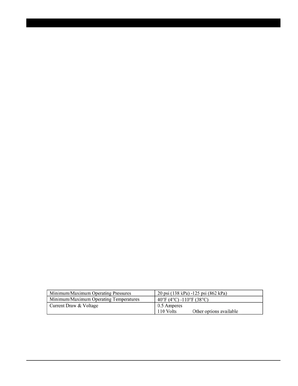
Table 1
System Specifications
 Loading...