Installation
Pre-Installation Checklist
1. A standard electrical outlet (120V/60Hz) must be
located within 12’ of the installation site.
2. A functioning floor drain, washer standpipe or
suitable location for waste water discharge must
be located within 20’ of the installation site.
(see General Warning #6 on page 4)
3. A working pressure reducing valve must be
installed on the inlet water line that supplies the
water softener. Note: The warranty is void if
the system is exposed to water pressure in
excess of 100 psi.
4. The temperature at the location of the water sof-
tener system must never be below 40°F.
Installation
1. Floor space: Make sure the floor space that has
been selected to install the water softener is clean
and on a level surface.
2. Leveling the salt container: If the floor
beneath the salt container is not level, do not use
shims or spacers to level the salt container. A
platform that supports the entire bottom surface
of the salt container must
be used.
3. What to bypass: A typical installation would
include bypassing the outside hose bibs. The cold
water feeding the kitchen sink may or may not be
bypassed depending upon preference.
4. Connection kit: The standard connection kit
supplied with the water softener will be a 3/4”
brass sweat connection kit (see Figure 1). Other
connection kits are available. (see Page 19)
This kit will consist of the following:
2 - Plastic nut 1” quick connect, black (#1)
2 - Plastic split ring, white (#2)
2 - O-Ring (#3)
2 - Brass connector 3/4” sweat (#4)
5. Plumbing preparation: Un-screw the two plas-
tic nuts (#1) and pull on the two brass connectors
(#4) to remove them from the bypass assembly.
Next remove the white plastic split rings (#2) and
the O-Rings (#3).
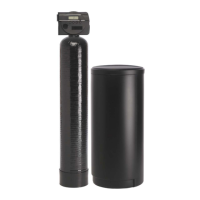
6. Solder at least 6” of pipe to the brass connectors
before re-assembly. (see Figure 2)
7. After soldering is complete, cool the pipe and con-
nectors. Slide the plastic nuts (#1) over the brass
connectors (#4). Place the white plastic split
rings (#2) into the grooves closest to the copper
pipe. Next place the O-Rings (#3) into the grooves
closest to the end of the brass connectors (#4). Re-
assemble the completed connection kit onto the
bypass assembly. (see General Warning #8 on
page 4)
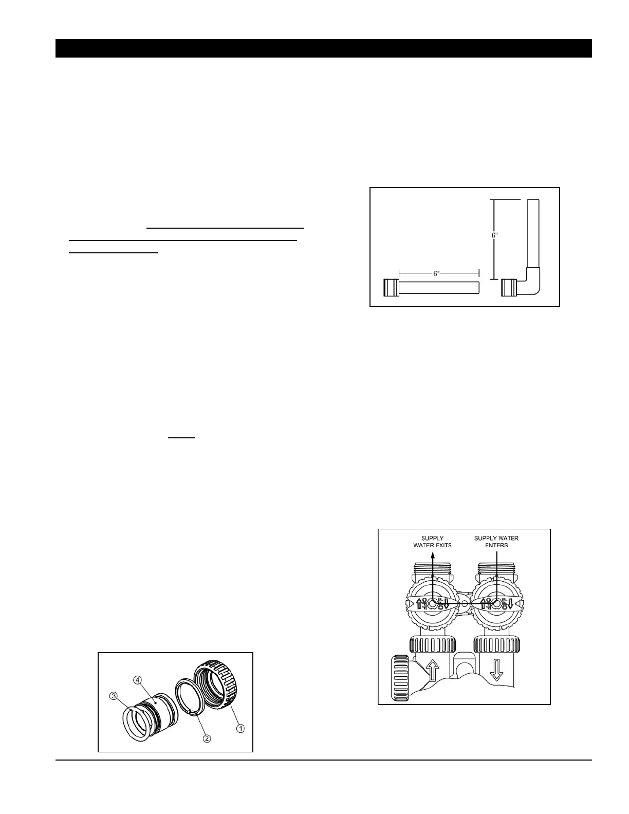
8. Plumbing: When connecting the water softener
to the existing plumbing, make sure the inlet
water is connected to the inlet of the softener.
Arrows on the valve body indicate direction of
flow. Make sure the bypass valves are in the
position shown in figure 3.
9. All plumbing should be done in accordance with
local plumbing codes. (see General Warning #1 on
page 4)
Page 5
Figure 1
Figure 2
Figure 3
 Loading...