Sentry Sample Sentry II 25
Electrical Connections
Electrical Shock Hazard – All input and output wiring should be installed in such a manner that
access to bare copper is prohibited during normal operation.
An access hole sized for ½" NPT (15 mm) electrical conduit tting is provided on the
bottom of the enclosure. A sealing type conduit tting is required to maintain the
enclosure’s rating.
Power Connection
The Sample Sentry II contains two circuit boards stacked in the enclosure. The power
connection is located on the output board, the bottom board in the circuit board stack.
The Sample Sentry II contains a universal power supply. The power supply is capable
of accepting an input voltage range of 100–240 VAC and frequency of 50 or 60 Hz. The
Sample Sentry II automatically operates with power supplied in this range. A power supply
lead of 16 AWG (1.3 mm²) copper wire is recommended.
The Sample Sentry II should be connected to an electrical outlet or outlet strip with surge
suppression and ltering. A suitable external over-current protection device such as a fuse
or circuit breaker (15 A) is recommended for both the hot (L) and neutral (N) leads. Using
this method, the plug serves as the disconnect device. The cord and plug shall comply
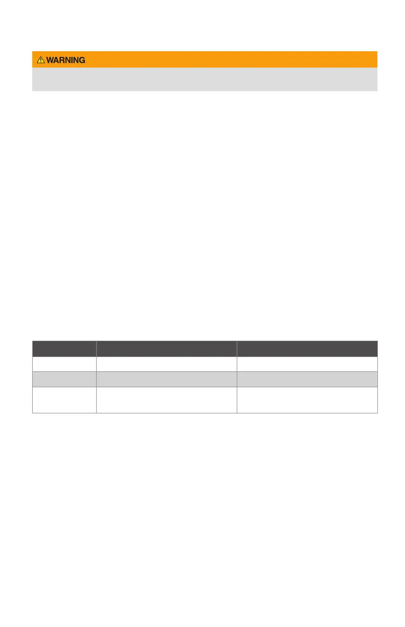
with the following standards:
Table 2. Power Cord Requirements
Location Cord Plug
United States ANSI/UL 817 ANSI/UL 498
Canada CSA C22.2 No. 21 or C22.2 No. 49 CSA C22.2 No. 21 and C22.2 No. 42
European
Community
IEC 60227 or 60245 Appropriate IEC standard
If desired, the Sample Sentry II may also be hard wired to instrument-quality power
using appropriate certied conduit, ttings, and wiring. A suitable external over-current
protection device, such as a fuse or circuit breaker (15 A), and disconnect device is
recommended. The over-current protection and disconnect devices shall be installed on
both the hot (L) and neutral (N) leads. The disconnect device shall be located near the
equipment and marked with appropriate ON(1) OFF(O) markings as specied by local
codes. For xed wiring methods, the ground conductor shall have green with a yellow
stripe as the insulation. Installation should be performed by qualied personnel in
accordance with local codes and procedures.