Operational Modes
DynaDrive 1525-BRS - User Guide Page 15
4.2 Velocity Mode
4.2.1 Velocity Mode – Factory Potentiometer Setting
To set the DynaDrive in the Velocity Mode, remove the cover to expose the Torque Mode
Jumper at J3. Remove the Torque Mode Jumper at J3 that is located right behind the Tach pot.
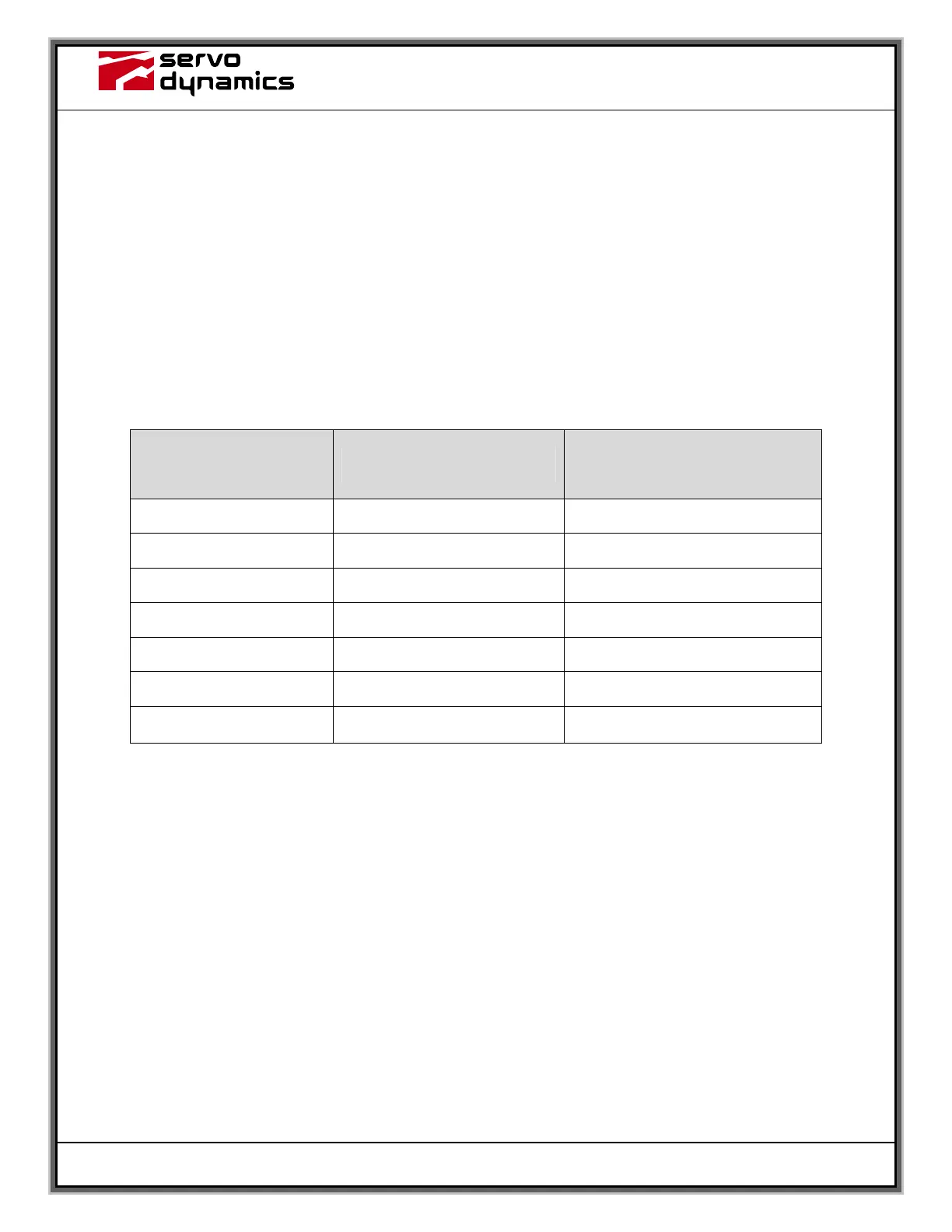
The pot settings must be adjusted for Velocity mode per Table 4 below. The Velocity mode
requires a tachometer feedback signal from the motor or motion control system.
To match the motor to the DynaDrive 1525-BRS, set the RMS and SIGNAL pots per Table 2.
Set the PEAK CURR LIMIT pot to full CCW. Set the remaining pots per Table 4 below. Now
perform the Velocity Mode Setup procedure on the next page.
Potentiometer
Description
Potentiometer
Setting
Potentiometer
Test Point
N/A N/A TP1 – Common
SIGNAL See Table 2 TP2 – SIGNAL
TACH 7.0 k Ohms TP3 – TACH
COMPENSATION Full CCW TP4 – COMPENSATION
PEAK CURR LIMIT Full CCW TP5 – PEAK CURR LIMIT
BALANCE No Preset None
RMS See Table 2 TP7 – RMS
Table 4: Velocity Mode POT settings
Note: All Measurements are with respect to TP1 (Common) with J1 removed.