Installation
DynaDrive 1525-BRS - User Guide Page 9
3.3 Connector Information
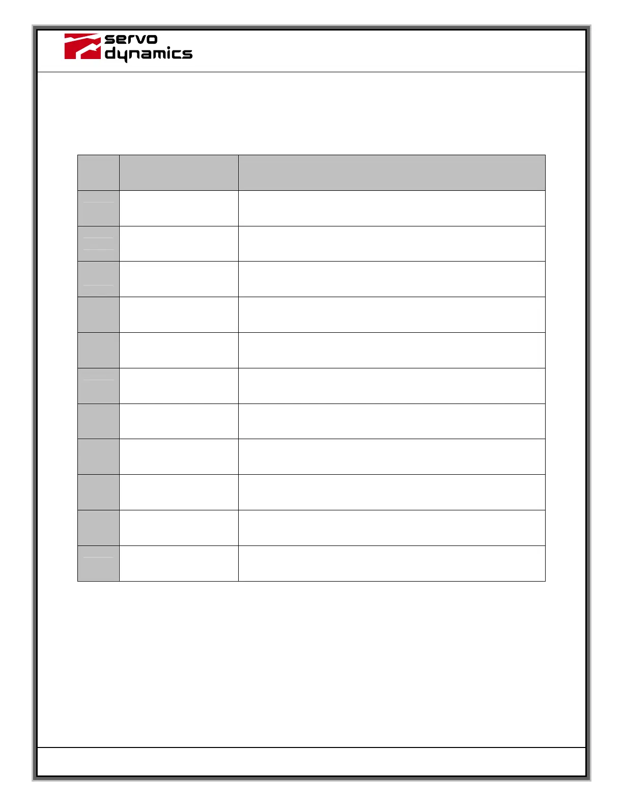
3.3.1 J1 – Control I/O Connection
J1 Label Description
1
COMMAND - Differential input
2
COMMAND +
Differential input. This pin can also be used as a single ended
input. Use J1, pin 2 as common.
3
COMMON
Connected to other commons and connected to the metalwork of
the amplifier mounting plate.
4
TACH IN
Single ended input that has additional tach filtering and
conditioning.
5
COMMON See pin 3 above.
6
LIMIT SWITCH -
Prevents motor overtravel in the CCW direction. Normally open,
unless J4 is installed
7
LIMIT SWITCH +
Prevents motor overtravel in the CW direction. Normally open,
unless J4 is installed.
8
INHIBIT/RESET
Internally pulled to + 12Vdc. Pull to common to inhibit and reset
amplifier.
9
CURR MONITOR OUT
Current monitor output. +/- 4 VDC out equals approx. +/- 25
amps.
10
FAULT OUTPUT
Normally pulled up to +12 volts thru a 10 K resistor. Will sink 10
mA max to ground when a fault occurs.
11
COMMON See pin 3 above.