18
4 Representative Systems
All Setcom Intercom Systems are delivered with a System Diagram specific to the components ordered. Be sure
to have this System Diagram in hand before starting your installation. If your intercom system was installed by the
apparatus original equipment manufacturer, the Setcom System Diagram should be included with your manual. If
you cannot locate the System Diagram specific to your installation, contact Setcom at 1-650-965-8020 ext. 603
and a copy can be emailed/faxed to you. On the following pages a number of the most commonly used system
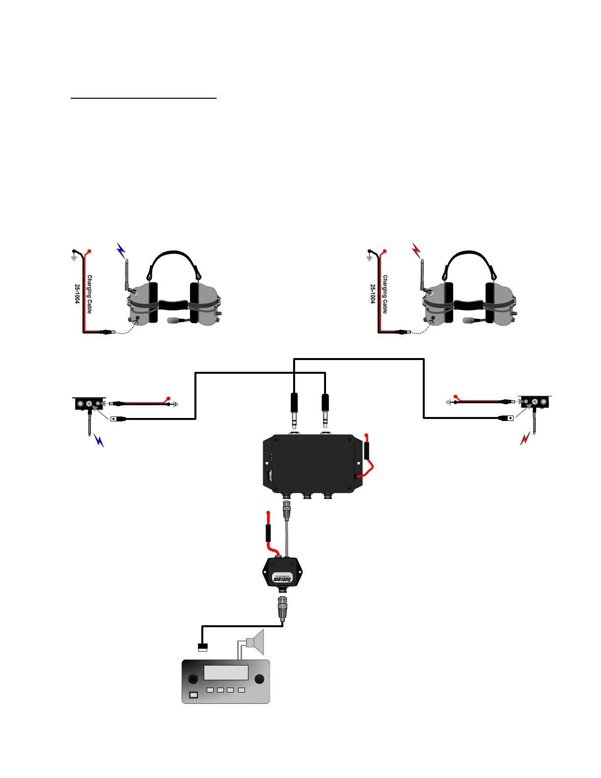
configurations are shown.
4.1 Two Crew Wireless
SYSTEM 900
HEADSET
HEADSET
FOOTSWITCH
RADIO REMOTES
PUMP
PANEL
POWER
IM-900
Intercom/Mixer
T
X
A
U
D
I
O
R
X
A
U
D
I
O
R
A
D
I
O
L
E
V
E
L
A
D
J
U
S
T
S
N
:
S
0
0
0
0
1
1
1
1
1
1 Amp
Fuse
RIM-900-BAL
Radio Interface Module
1 Amp Fuse
Driver Captain
25-0735-xx
25-0735-xx
B+
(12Vdc)
B+
(12Vdc)
Radio Cable
900W3-BASE
25-1004
GND
B+
(12Vdc)
900W3-BASE
25-1004
GND
B+
(12Vdc)
GND
B+
(12Vdc)
CSB-900W3
Wireless Headset
GND
B+
(12Vdc)
CSB-900W3
Wireless Headset
Radio
468.725