Do you have a question about the SEW-Eurodrive MOVITRAC B MC07B0022-5A3-4-00/S0 and is the answer not in the manual?
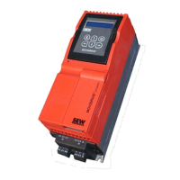
| Category | Inverter |
|---|---|
| Input Voltage | 3-phase, 380-480 V AC |
| Frequency range | 0-400 Hz |
| Protection Class | IP20 |
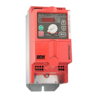
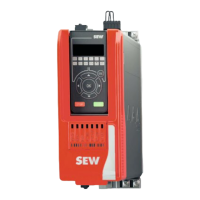
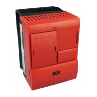
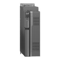
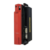
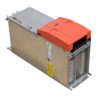
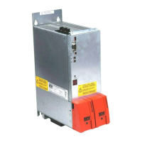
| Type | MOVITRAC B |
| Control Method | Sensorless vector control (SVC), V/f control |
| Control type | Sensorless vector control |
| Ambient temperature | -10 to 50 °C |
| Communication interface | RS485 |
Describes the key functions and properties of MOVITRAC® B inverters.
Provides general technical specifications applicable to all MOVITRAC® B inverters.
Presents an overview of MOVITRAC® B technical data, including size and power connections.
Describes the two slots for pluggable modules that add functionality to MOVITRAC® B.
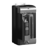
Details the DBG60B keypad and its functions for diagnostics and parameter setting.
Explains fieldbus connection options and gateways for MOVITRAC® B.
Introduces the MOVI-PLC® controller and its unit types.
Explains SEW-EURODRIVE's control technology options: MOVI-PLC® and CCU.
Explains how parameters are set and introduces symbols used for parameter explanation.
Provides a comprehensive list of all parameters, their index, name, and range/factory setting.
Outlines the systematic steps for project planning, from clarification to component compilation.
Describes common application scenarios like trolleys and hoists.
Explains the speed-torque characteristic curve and its limitations.
Provides recommendations and guidelines for selecting the correct motor.
Explains how MOVITRAC® B inverters calculate and manage load on the output stage.
Covers project planning for explosion-proof motors, requiring specific SEW-EURODRIVE approval.
Guides the selection of braking resistors, including parallel connection and peak braking power.
Guides on connecting AC brakemotors to the SEW brake system.
Covers permitted voltage supply systems and line contactor/fuse requirements.
Discusses multi-motor and group drives, including motor currents and cable lengths.
Covers EMC compliance, interference immunity, and emission limits.
Provides important notes and installation instructions for HF output filters.
Explains how to operate two motors on one inverter using different parameter sets.
Illustrates the priority of operating states and the interrelation of control signals.
Explains the basic structure and application of the PI controller.
Presents application examples, assuming correct unit startup.
Explains the purpose and scope of the documentation for installation, startup, and service.
Covers general safety information regarding operation, handling, and installation of frequency inverters.
Specifies the designated use of frequency inverters and applicable standards (EU/EFTA).
Covers installation requirements, protection from strain, and prohibited applications.
Guides electrical connection, observing national guidelines and EMC requirements.
Covers operation safety, including monitoring devices and avoiding contact with live parts.
Provides a wiring diagram showing connections for power supply, motor, options, and control signals.
Explains how to enable the motor via terminals after exiting manual operation.
Provides a comprehensive list of errors (F00-F113), their possible causes, and suggested measures.