EasyManua.ls Logo

SEW-Eurodrive S77 User Manual

SEW-Eurodrive S77
68 pages
To Next Page IconTo Next Page
Page #1 background imageLoading...
Page #1 background image
04/2000
Gear Units
R..7, F..7, K..7, S..7 Series, Spiroplan
®
W
Edition
05/2001
Operating Instructions
10503013 / EN

Questions and Answers:

SEW-Eurodrive S77 Specifications

General IconGeneral
SeriesS77
Gear Unit Size77
Input OptionsIEC motor
Protection ClassIP65
Cooling MethodNatural Convection
LubricationOil

Summary

Safety Notes

Preliminary remarks

General introduction to safety notes and precautions for geared motors.

General

General safety information regarding moving parts, hot surfaces, and qualification of personnel.

Gear Unit Design

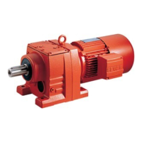
3.1 Basic design of a helical gear unit

Illustrates the basic structure and components of a helical gear unit.

3.2 Basic design of a parallel shaft helical gear unit

Details the design and components of a parallel shaft helical gear unit.

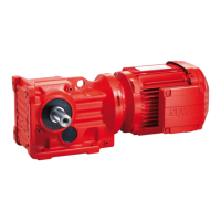
3.3 Basic design of a helical-bevel gear unit

Explains the design principles and parts of a helical-bevel gear unit.

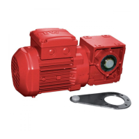
3.4 Base design of a helical-worm gear unit

Presents the fundamental design and components of a helical-worm gear unit.

3.5 Basic design of a SPIROPLAN® gear unit

Shows the design principles and components for a SPIROPLAN® gear unit.

Mechanical Installation

4.2 Before you begin

Prerequisites and conditions that must be met before starting the installation process.

4.4 Installing the gear unit

Instructions for mounting the gear unit or geared motor onto a support structure.

4.5 Gear units with solid shaft

Guidance on installing input and output elements onto solid shaft gear units.

4.6 Installation of torque arms for shaft-mounted gear units

Procedures for installing torque arms on different types of shaft-mounted gear units.

4.7 Installation/removal of shaft-mounted gear units with key or splines

Steps for installing and removing gear units that use keys or splines for shaft mounting.

Removal notes

Procedures for removing gear units that were installed with the SEW mounting/removal kit.

4.8 Installation/removal of shaft-mounted gear units with shrink disc

Steps for installing and removing gear units that use a shrink disc for shaft mounting.

4.9 Installation of the AM adapter coupling

Instructions for installing the AM adapter coupling for IEC and NEMA adapters.

4.10 Installation of the AQ adapter coupling

Procedures for installing the AQ adapter coupling (AQA and AQH designs).

4.11 Installation on the AD input shaft assembly

Steps for installing onto the AD input shaft assembly with motor mounting platform.

AD../ZR design with centering shoulder

Details for installing components on AD../ZR designs with a centering shoulder.

Startup

5.1 Startup of helical-worm and Spiroplan® W gear units

Specific startup notes and running-in periods for helical-worm and Spiroplan® W gear units.

5.2 Startup of helical, parallel shaft helical and helical-bevel gear units

Startup notes for helical, parallel shaft helical, and helical-bevel gear units.

Troubleshooting

6.1 Gear unit problems

A table outlining common gear unit problems, possible causes, and remedies.

Inspection and Maintenance

7.1 Inspection and maintenance periods

Schedule and tasks for regular inspection and maintenance of gear units.

7.2 Lubricant replacement schedule

Chart showing lubricant replacement intervals based on operating hours and temperature.

7.3 Inspection/maintenance of gear units

Detailed procedures for checking and changing oil in gear units.

Checking the oil level

Steps for checking the oil level in the gear unit.

Changing the oil

Step-by-step guide on how to drain and refill the gear unit with new oil.

Mounting Positions

8.3 Mounting positions, helical gear units

Diagrams illustrating mounting positions (M1-M6) for helical gear units (R..).

RF17-RF167

Mounting position diagrams for RF17-RF167 series geared motors.

R17F-R87F

Mounting position diagrams for R17F-R87F series gear units.

RX57-RX107

Mounting position diagrams for RX57-RX107 series gear units.

RXF57-RXF107

Mounting position diagrams for RXF57-RXF107 series gear units.

8.4 Mounting positions, parallel shaft helical gear units

Diagrams showing mounting positions for parallel shaft helical gear units (F..).

FF/FAF/FHF/FAZ/FHZ27-157, FVF/FVZ27-107

Mounting position diagrams for FF, FAF, FHF, FAZ, FHZ, FVF, FVZ series gear units.

FA/FH27-157, FV27-107

Mounting position diagrams for FA, FH, FV series gear units.

8.5 Mounting positions, helical-bevel gear units

Diagrams illustrating mounting positions for helical-bevel gear units (K..).

8.6 Mounting positions, helical-worm gear units

Diagrams showing mounting positions for helical-worm gear units (S..).

Lubricants

Lubricant fill quantities

Recommended lubricant fill quantities in liters for various gear unit types and mounting positions.

Related product manuals