Do you have a question about the SEW MOVIDRIVE MDX60B and is the answer not in the manual?
Guidance on effectively using the operating instructions for assembly, installation, startup, and service.
Explanation of the systematic design of safety notes, including signal words and consequences.
Details on how adherence to operating instructions is required for warranty claims.
Information on SEW-EURODRIVE's liability limitations regarding non-observance of instructions.
Legal notice regarding copyright and prohibition of unauthorized duplication or modification.
Basic safety guidelines to prevent injury and damage, emphasizing careful reading and understanding.
Defines qualified personnel authorized for installation, startup, and service tasks.
Specifies intended use of drive inverters and compliance with relevant directives and standards.
Notes on proper handling during transportation and storage, including climatic conditions.
Instructions for installing units according to regulations and preventing strain or damage.
Guidance on electrical installation, compliance with regulations, and EMC considerations.
Information on unit compliance with requirements for safe disconnection of power and electronic connections.
Safety guidelines for operating systems with integrated drive inverters.
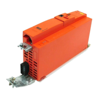
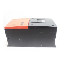
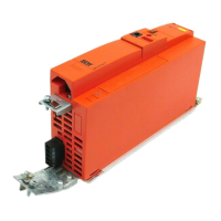
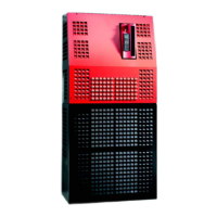
Details on unit identification, system nameplates, and the scope of delivery for different sizes.
Lists the standard components included in the scope of delivery for various unit sizes.
Technical and connection details specific to MOVIDRIVE® MDX60/61B size 0 units.
Technical and connection details specific to MOVIDRIVE® MDX61B size 1 units.
Technical and connection details specific to MOVIDRIVE® MDX61B size 2S units.
Technical and connection details specific to MOVIDRIVE® MDX61B size 2 units.
Technical and connection details specific to MOVIDRIVE® MDX61B size 3 units.
Technical and connection details specific to MOVIDRIVE® MDX61B size 4 units.
Technical and connection details specific to MOVIDRIVE® MDX61B size 5 units.
Technical and connection details specific to MOVIDRIVE® MDX61B size 6 units.
Technical and connection details specific to MOVIDRIVE® MDX61B size 7 units.
Comprehensive guide covering all aspects of installing the basic MOVIDRIVE® unit.
Specifies essential clearance and orientation requirements for proper installation and cooling.
Recommendations for routing power and signal cables in separate conduits for organization.
Guidance on input fuses and recommendations regarding earth-leakage circuit breakers.
Detailed instructions and requirements for protective earth (PE) connection according to standards.
Considerations for operating on TN and TT systems, and specific notes for IT networks.
Specifications for appropriate cable cross-sections for supply, motor, and signal cables.
Important notice regarding potential damage from connecting capacitive loads.
Instructions for mounting specific types of braking resistors.
Information on the electrical isolation and protection of binary inputs and outputs.
Guidelines for ensuring electromagnetic compatibility through proper cable shielding and grounding.
Specific instructions for installing the MOVIDRIVE® units of size 6.
Specific instructions for installing the MOVIDRIVE® units of size 7, including lifting.
Details on the optional mounting base and associated hardware for size 7 units.
Instructions for using the wall bracket to mount MOVIDRIVE® B size 7 units.
Information on installing the DLK11B air duct for heat dissipation in size 7 units.
Technical data and installation instructions for the DC link adapter 2Q.
Technical data and installation instructions for the DC link adapter 4Q.
Instructions for connecting two inverters using the DLZ11B DC link coupling.
Step-by-step instructions for safely removing and installing the DBG60B keypad.
Procedure for removing and reinstalling the front cover of the unit.
Details on UL approval, field wiring power terminals, and short-circuit current ratings.
Instructions for installing shield clamps for power and signal cables on various unit sizes.
Guidance on installing touch guards to achieve IP20 protection for power terminals.
Detailed wiring diagrams for the power section, brake, and signal terminals of the basic unit.
Table showing assignments for braking resistors, chokes, and filters based on unit size and type.
Instructions and specifications for connecting to the system bus (SBus 1).
Guidance on connecting to the RS485 interface for communication.
Technical data and connection instructions for DWE11B/12B interface adapters for encoders.
Instructions for connecting the UWS21B option for RS232 communication with a PC.
Instructions for connecting the USB11A adapter for USB communication with a PC.
Overview of possible combinations and arrangements of option cards for MDX61B units.
Procedure and important notes for installing and removing optional cards.
General installation notes and procedures for connecting encoders and resolvers.
Detailed connection and terminal information for the DEH11B HIPERFACE® encoder option.
Detailed connection and terminal information for the DEH21B absolute encoder option.
Detailed connection and terminal information for the DEU21B multi-encoder card option.
Detailed connection and terminal information for the DER11B resolver option.
Information on connecting external encoders to the X:14 connector on DEH11B/DER11B.
Procedures for connecting encoders to the DEH11B option based on motor types.
Instructions for using connector X14 for incremental encoder simulation output.
Guidance on establishing master/slave connections using connector X14.
Details on the DIO11B input/output card, including terminals and functions.
Details on the DFC11B CAN-Bus interface option, including connection and addressing.
Overview of requirements, parameters, operating modes, and combinations for successful startup.
Essential preparatory steps and considerations before commencing the startup procedure.
Detailed guide for performing startup using the DBG60B keypad.
Step-by-step instructions for initiating and completing the startup process via the keypad.
Procedure for configuring and starting up the speed controller function.
Instructions on how to navigate and adjust parameters within the parameter mode.
Introduction to using the MOVITOOLS® MotionStudio software for unit operations.
Basic procedures for starting the software, establishing communication, and scanning the network.
Specific safety notes and settings for starting up HTL motor encoders with MOVIDRIVE® MDX61B.
Instructions and diagrams for starting the motor using analog setpoints and fixed setpoints.
A comprehensive list of all available parameters, their settings, and factory defaults.
Explanation of the unit's operating status indicated by the 7-segment display and other indicators.
Information on the DC link voltage display behavior for size 7 units.
Description of basic displays and information messages shown on the DBG60B keypad.
List of information messages displayed on the DBG60B or in MotionStudio, with their descriptions.
Detailed explanation of keypad functions including key assignments and parameter copying.
Procedure for navigating and setting parameters using the DBG60B keypad.
How to display and edit H variables in the variable mode using the DBG60B keypad.
Instructions for accessing and managing the user menu for frequently used parameters.
Step-by-step guide to adding parameters to the user menu via the DBG60B keypad.
Procedure for removing parameters from the user menu using the DBG60B keypad.
How to select and save a parameter that is displayed upon unit startup.
Overview of IPOSplus® programming requirements and keypad variable editing.
Information on the pluggable memory card for storing basic data and quick unit replacement.
Important considerations and potential error messages when replacing the memory card.
Details on the fault memory, switch-off responses, and methods for resetting errors.
Explanation of error message display sequences and suberror codes.
A comprehensive list of error codes, their designations, possible causes, and recommended measures.
Information on contacting SEW-EURODRIVE electronics service for repair assistance.
Recommendations for maintaining unit service life during extended storage periods.
Instructions for proper disposal of the unit's components in accordance with regulations.
Details on product compliance with CE, UL, and C-Tick standards and directives.
Lists applicable technical data for all MOVIDRIVE® MDX60B/61B inverters.
Detailed technical specifications for AC 400/500 V units across various sizes.
Detailed technical specifications for AC 230 V units across various sizes.
General electronics data, including terminal descriptions and specifications.
Physical dimensions and drawings for MOVIDRIVE® MDX60B units of various sizes.
Physical dimensions and drawings for MOVIDRIVE® MDX61B units of various sizes.
Technical specifications for various encoder and braking resistor options.
Technical data for the DIO11B input/output card and DFC11B CAN-Bus interface.
EC Declaration of Conformity for the MOVIDRIVE® series.
EC Declaration of Conformity for MOVIDRIVE® units with DFS11B/DFS21B options.
EC Declaration of Conformity for MOVIDRIVE® units with DCS21B/DCS31B options.
Contact information for SEW-EURODRIVE GmbH & Co KG headquarters in Bruchsal, Germany.
Contact details for SEW-USOCOME production facilities in France.
Contact details for SEW-EURODRIVE INC. production facilities in the USA.
Contact details for SEW-EURODRIVE AB assembly operations in Sweden.
Contact details for SEW-EURODRIVE JAPAN CO., LTD assembly operations in Iwata, Japan.
| Series | MOVIDRIVE |
|---|---|
| Type | MDX60B |
| Category | Inverter |
| Protection Class | IP20 |
| Control Method | V/f control, vector control |
| Communication Interfaces | CANopen, PROFIBUS DP |
| Ambient Temperature Range | -10°C to +50°C |
| Relative Humidity | ≤ 95 %, non-condensing |
| Dimensions (W x H x D) | Varies by model |
| Weight | Varies by model |